Amp Eater Notes
Shaft drive assembly hardware
From instructions:COMMENT: The following lists the items required for the shaft drive assembly as noted alphabetically on Plansheet 3 of 4. Most parts are available from GLEN-L with the respective part numbers noted. See the GLEN-L On-Line "Inboard Hardware" catalog for prices and more details.
"A" RUDDER: Part No. 90-019. Rudder
size approximately 9" x 9" with 1"
shaft.
"B" RUDDER STUFFING: Part No.
90-102. A Rudder Stuffing Box acts as a bearing and
prevents water from entering the boat around the rudder
shaft. Locate atop blocking #12 so the lower section
protrudes approximately 1/4" below the boat
bottom.
"C" TILLER: Part No. 90-028. A
7" tiller arm is keyed or otherwise held securely to the
rudder shaft. The tiller can be mounted directly atop the
rudder post bracket bearing and act as a collar to hold the
rudder in place. Optional, and better practice, is to use a
safety collar with set screw (GLEN-L Part No. 90-400)
to prevent the Rudder from sliding out.
"D" RUDDER SHAFT SUPPORT: The upper portion
of the rudder shaft must be adequately supported to prevent
side motion. The rudder post shelf, described under #12, can
be made of oak or other hardwood bored to match the rudder
diameter and used as a bearing. However, a commercially
available bronze or nylon bearing is more durable.
"E" STERN BEARING: Part No. 92-700. A
stern bearing is the underwater aft bearing that supports the
prop shaft and bolts to the skeg aft end blocking with
hanger, lag, or through-bolt as shown on the pattern. Counter
bore the aft end blocking as required to fit flush to the
skeg, and the aft end of the PVC tube butts to the stern
bearing casting. The metal sleeved rubber bearing is a
separate item for inserting in the stern bearing casting
(Part No. 93001) for a 1" prop shaft.
"F" PROP SHAFT: Part No. 90-734. The
1" prop shaft is keyed, tapered, and threaded to
accommodate a standard propeller and the opposite end keyed
for the drive pulley. Overall length should be approximately
44", however, take the actual measurement directly from
the work.
"G" PROP NUT KIT: Part No. 90-723.
Lock the prop to the shaft with a key, nut, and cotter
key.
"H" THRUST BEARING: The self aligning thrust
bearing is for a 1" shaft with eccentric (or other)
locking collar. It is bolted to a 2" x 6" x width
to suit member that in turn through-bolts to the Thrust
Blocking #14. See #14 pattern. Position the thrust bearing so
the prop shaft turns freely through it and the stern bearing
; it must spin with the least resistance possible.
"I" STUFFING BOX: Part No. 90-234. A
seal type stuffing gland for a 1" shaft is mounted on
the forward inside end of the PVC shaft tube and coupled to
it with a rubber hose. Trim the tube length to be minimal but
adequate for the rubber coupling hose with two clamps. The
hose is Part No. 90-232 and the clamps Part No.
90-818 (3 required). Leave the hose clamps holding the
stuffing box to the shaft tube loose, install the prop shaft,
rotate it, and allow the hose to adjust the stuffing box for
least resistance; then tighten the two clamps on the shaft
tube and the one on the stuffing box. Grease the stuffing box
bearing through the fitting and recheck the shaft alignment.
It is important that the shaft rotates freely, without
binding, in the stern bearing, stuffing box, and thrust
bearing.
"J" PROPELLER (PROP): The maximum propeller
diameter for the shown skeg and shaft angle is 11" with
the pitch varying with the prop shaft rpm and motor
horsepower. The prototype used an 11" X 12" three
blade prop turning 830 rpm.
The Following is for estimating only. Prices are current as of October 2012. Check on-line Inboard Hardware catalog for current prices.
| Part # | Quan | Price each |
|---|---|---|
| 90-019 | 1 | 275.00 |
| 90-102 | 1 | 106.50 |
| 90-028 | 1 | 43.00 |
| 90-400 | 1 | 11.25 |
| 92-700 | 1 | 163.31 |
| 93-001 | 1 | 81.30 |
| 90-734 | 1 | 175.00 |
| 90-723 | 1 | 5.40 |
| 90-234 | 1 | 35.25 |
| 90-232 | 1 | 12.95 |
| 90-818 | 3 | 6.30 |
| $915.26 | ||
A typical wiring diagram
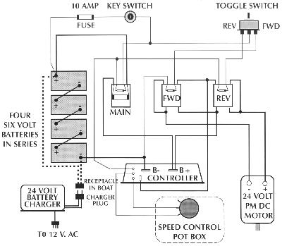
Note: While this is the wiring diagram for the equipment we used on the Amp Eater, it will not apply to all variations of hardware that can be used. Refer to the literature that comes with the components you use. Do not try to impose this wiring on your components unless it matches the recommendations of your equipment manufacturer. A Curtis pulse modulator controler was used in the above set up.
Electrical components used on the test model
-
Motor: Pacific Scientific, 24 volts DC, 1 hp, 1750
rpm
Cat #BAF 3644-5081-48B, Continuous duty -
Controller: Curtis-PMC #1204-001
24-36 VDC/275 A