
.....running rigging
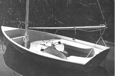 |
| FIG. 5-1-This neatly rigged boat (Glen-L 11) is ready to receive the sails. The running rigging is clearly shown. This mainsheet rig is like that shown by Fig. 5-4. The clew outhaul slides on a track with a line securing it to a jam cleat on the side of the boom. The aluminum tubing boom is held in position by the main halyard. The main and jib halyards are neatly coiled in position on the mast. Note the tracks with sliding cam cleats on each side of the centerboard for controlling the jib sheets. |
INTRODUCTION
The RUNNING RIGGING consists of the lines used for hoisting and controlling the sails directly, or indirectly such as through control of the boom. The boat in Fig. 5-1 shows many of the lines used for the running rigging in position. The running rigging moves about the boat, or can be moved. The LINES are usually made from ROPE. Once the rope becomes operational in the boat, it is then referred to as a "line". This then is the difference between line and rope. Most lines on small sailboats are made from synthetic twisted or braided rope, such as polyester or polypropylene. Nylon is usually not a good line because it stretches too much. Ropes of natural materials such as hemp are seldom used anymore. Wire rope is sometimes used for some running rigging, but must be connected to rope at the moving ends that must be handled. A type of rope made especially to be easy on the hands is called "YACHT BRAID" or other similar proprietary name, and is more costly than the normal braided line. Rope sizes are commonly noted by the approximate diameter of the rope, even though it was once common to give the size by the circumference.
HALYARDS
The lines used for hoisting and lowering the sails are called HALYARDS. The halyards run up and down the mast across a sheave (pronounced "shiv") at or near the top of the mast. Halyards that are outside the mast are called "external" halyards, and those that run inside a hollow mast are called "internal" halyards. Halyards on small boats can be made of rope, and often stainless steel wire rope is also used. When wire rope is used, it should be the flexible type such as 7 x 19. In the case of wire rope halyards, a portion of braided or twisted rope must be attached to the running end so the crew can handle the halyard without injuring their hands. The braided rope is then attached to the wire rope either with a Nicopress eye, or by a special splicing. On large boats, special halyard winches designed for wire rope preclude the need for a rope tailing.
Several methods are used to attach the halyards to the head cringle of the sails. Probably the most common method is the use of a SHACKLE, a "U"-shaped fitting with an openable pin at the open portion of the "U" which passes through the head cringle (see Fig. 6-2). The halyard is attached to the shackle either with a spliced eye, Nicopress eye, or it is sometimes merely tied by a knot. A better method when wire rope is used is to use a ball joint with the shackle fitted onto the wire rope halyard before the ball has been swaged on (see Fig. 4-2 'a'). When wire rope halyards are used with a ball joint, a HALYARD HOOK should be used near the masthead. This fitting prevents hoisting the sail beyond a predetermined point up the mast. Sometimes an additional halyard hook is located near the mast base for the running end of the wire rope halyard with another ball swaged at this end to secure the halyard.
Another method used to attach halyards to sails is with BRUMMEL HOOKS (as shown in Fig. 5-2). These are special patented fittings used in pairs which allow quick attachment once you get the hang of using them. The Brummel hooks come in a wide variety of sizes and types which can be used for other situations as well as with halyards. One hook passes through the cringle at the head of the sail, and another goes through the eye at the end of the halyard, or can be merely knotted to the halyard. The two connect with a twist of the wrist.
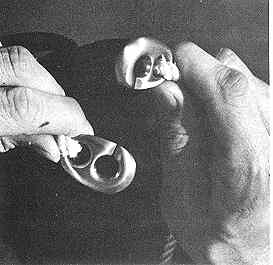
FIG. 5-2-Brummel hooks are patented fittings used in pairs. They are used to secure lines together or lines to other items such as sails. A twist of the two hooks is all that is required to join or release them. |
SHEETS
The lines used to control the trim or position of the sails are called SHEETS. The line used to control the mainsail is called the MAINSHEET, and the line used to control the jib is called the JIB SHEET. Rope is used for the sheets, and "yacht braid" type is often used because it is easier on the hands and does not kink or jam as easily as twisted rope. Because the force of the wind on the sails is often greater than the strength of the crew, it is often necessary for the sheets to have a built-in "mechanical advantage." This is where the various blocks (or "pulleys") and winches come onto the scene in various configurations to ease the work of the crew.
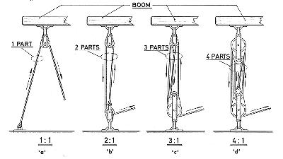
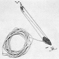
FIG. 5-3 - Various tackle configurations. The power of a tackle depends on the number of "parts" in the tackle. Actually, 'a' is not really a tackle as the block merely changes the direction of the line, thereby affording no gain in power. Fiddle blocks are shown for clarity where two sheaves are used, though double blocks, with side by side sheaves, would give the same result. The arrows show the direction the line will move when pulled. |
|
When the sheets are lead through a system of blocks, a TACKLE is formed that, depending on the number of "parts," will decrease the effort required to do the work. This is called "mechanical advantage" and is shown by Fig. 5-3. All main sheet configurations are nothing more than variations on these basic tackles, even though the location of the various blocks may disguise the number of parts used in the tackle. In figuring a tackle, it is usual to deduct 10% from each "part" per block to allow for the friction caused at the sheave in the block. Also note that the more parts in a tackle, the more line you must have and consequently the more line you will have to pull through the tackle to move the object a comparable distance. Sheet rig types come in an infinite variety of configurations, and some of the more common main and jib sheet rigs have been shown in Figs. 5-4 through 5-13. To run the sheet through the blocks is to REEVE the sheet, and it is a good practice to knot the running end of all sheets so they will not inadvertently pass through and out the blocks, causing loss of control of the sails. |
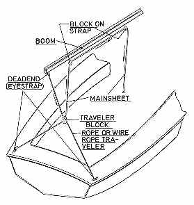
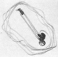
FIG. 5-4 - Ratio 2:1. A simple mainsheet set-up which uses a rope or wire rope traveler. Although the traveler is shown deadending to eye straps, one end could be made adjustable by belaying to a jam cleat. The mainsheet can be held by hand or a block or cam cleat can be used as shown in Fig. 5-5. |
|
Note that in many cases the mainsheet forms, or is used in conjunction with, the TRAVELER. The traveler lets the mainsheet rig or unit move or "travel" from one side of the boat to the other. Travelers can range from the combination mainsheet/ traveler type, or a simple length of line, or very elaborate fittings complete with tracks using blocks with ball or roller bearings and lines to control them. 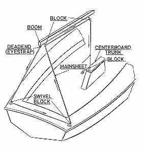
FIG. 5-5 - Ratio 3:1. The mainsheet is used as the traveler in this rig. |
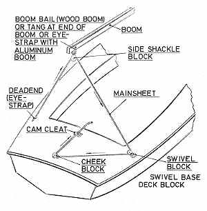
FIG. 5-6 - Ratio 2:1. This mainsheet is also used as the traveler, but requires at least some aft deck area. The main feature of this layout is the minimum of hardware required. Because the sheeting lead on the boom is at the aft end, roller reefing can easily be incorporated by hanging the side shackle block from a swiveling tang on the end of the boom. |
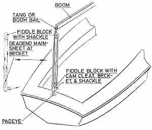
FIG. 5-7 - Ratio 4:1. This mainsheet rig is handy to use where roller reefing is desired. It would be possible to mount the lower fiddle block to a track so it could to move each side with the boom, acting as a traveler. If roller reefing is not used, the mainsheet arrangement could be located at some location along the boom, although this would increase the effort required to move the boom. |
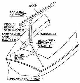
FIG. 5-8 - A system similar to Fig. 5-7, but using a rope or wire traveler similar to Fig. 5-4. This arrangement could also be located at the end of the boom for use with roller reefing. A cam cleat could be used at the swivel block so that the line need not be hand held. |
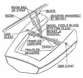
FIG. 5-9 - A rather elaborate system in that the traveler can be adjusted with lines each side via cam cleats. The fiddle block with cam cleat is used so that the line need not be hand held. |
Winches ease the work required in pulling or trimming the sheets, such as on jib sheets, as in Fig. 5-13. A winch gains mechanical advantage due to its gear ratio, diameter of the handle, and by the drum diameter of the winch. To determine the mechanical advantage (or power ratio), use the following formula: Radius of handle divided by the Radius of the drum X the Gear ratio = Power ratio. This means that power can be gained by either increasing the gear ratio, or radius of the handle, or decreasing the drum radius, or a combination of all three. Usually the drum radius should not be decreased because the winch will then do the work more slowly. On small boats such as being discussed here, most winches will not have gears and are thus referred to as "direct drive" winches such as shown in Fig. 5-14. Often used on small boats are winches which do not have handles either, and these are called "snubbing" winches (Fig. 5-15). Winches are usually relatively expensive items, and because mechanical advantage can be gained by other means, they are considered "deluxe" equipment on boats under about 25' in length.
|
FIGS. 5-10 through 5-13 show various jib sheet configurations. Jib sheets are usually two part lines secured at the mid length to the jib clew cringle usually via a shackle. This means that the hardware to control one side of the jib sheet will be duplicated for the other side; in other words, each side of the boat will have the fittings shown. |
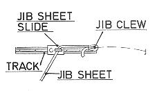
FIG. 5-10-A fairlead on a slide allows adjustment of the jib sheet lead point via the track. The sheet can be hand held or belayed to a cleat at some convenient point. |
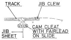 FIG. 5-11-Similar to the foregoing but the line is belayed with a cam cleat mounted directly on a slide which runs on the track. |
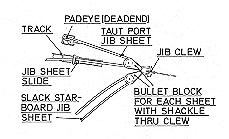
FIG. 5-12 - This system provides a power advantage of 2 to 1 (before allowing for fiction) to the jib sheet. The pad eye is mounted outboard of the track and two bullet blocks are shackled to the sail (one for each sheet for each side of the boat). The line then passes through a fairlead slide on a track and then aft to a jam or cam cleat. Optionally, the cam cleat could be mounted on the slide as for Fig. 5-11. |
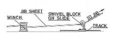
FIG. 5-13 - This jib sheeting method gains power through the use of a winch. The power of such a rig is directly dependent on the power of the winch that can be varied to suit. A fairlead on a slide could be used on the track, however, the swivel block reduces friction and chafe. A snubbing winch is shown in this example, although a winch with a handle can be used. The line must be belayed to a cleat beyond the winch. Note that the lead from the swivel block to the winch is fairly horizontal, as it should be. |
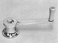
FIG. 5-14 - This is a typical example |
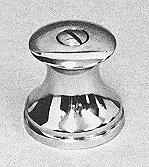
FIG. 5-15 - A typical snubbing winch as used for jib sheets on small sailboats. No handle is used. |
JIB SHEET LEAD
The sheet used to control the jib must be lead to a point on the boat that affords optimum setting of the jib (if one is used). If a Genoa jib is used, a separate sheet lead must be determined for this sail also. Since the jib sheets are in two parts (one for starboard, and the other for port), a lead point will be located on each side of the boat. In determining the lead points, the designer probably uses a formula similar to that shown in Fig. 5-16, which is at best always an approximation. Because methods used to determine jib sheet leads are approximations, and because no two sails will trim the same, it is best to make the sheet lead point adjustable by using lengths of tracks and sliding fittings attached to them. Another method for determining the jib sheet lead, at least on small boats, is to actually sail the boat with the jib in position and thereby determine the optimum setting in actual use. When the optimum point has been located, mark with a pencil and attach the appropriate fittings to the deck.
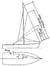
FIG. 5-16 - A common method used for locating the jib and Genoa sheet leads is graphically shown. The results are usually acceptable, but it is wise to use tracks so minor variations in sheet lead can be made. |
DOWNHAULS AND BOOM VANGS
Not all boats use downhauls or boom vangs, but they are used enough to warrant discussion. A DOWNHAUL is merely a line used to haul down on something, usually the tack of the sail, or the boom where the tack of the sail is located (see Fig. 3-12). A boom downhaul fitting or eye is often a part of the sliding gooseneck, to which the downhaul is attached to prevent the gooseneck from sliding up the mast. Once the sail has been hoisted with the halyard and pulled taut to a cleat, the downhaul can be used to gain further tension along the luff of the sail by pulling down and making fast to a cleat. Naturally, a similar downhaul could be used on the jib. A special type of downhaul called a "CUNNINGHAM" requires that the sail have an additional cringle usually located several inches above the tack cringle. The "Cunningham" is usually used on competition boats where more shape control of the sail is desired along the luff, but because of the racing rules, the boom cannot be hauled down below a certain pre-designated point.
A BOOM VANG (also called a "go faster" and "kicking strap") is a device that performs several functions. The boom vang is a tackle arrangement (see Figs. 5-17 and 5-18) connected at one end to the mast near its base, and with the other end preferably about 1/3 the distance of the boom aft of the mast. The boom vang helps take the undesirable "twist" out of the sail on all courses off (or away) from the wind, flattens the mainsail on a tack (sailing in the direction of the wind), and prevents the boom from lifting in case of accidental jibes (the boom moving rapidly from one side to the other when sailing downwind).
 |
 |
|
FIG. 5-17 & 5-18 - Two boom vang tackles with fittings. The upper block is attached to the boom, while the lower block is fastened to the mast base or near the mast base on deck. These boom vang tackles could also be used for mainsheet rigs if desired. Fig. 5-17 (left) has a power ratio of 3 to 1. Fig. 5-18 (right) has a power ratio of 4 to 1. |
|
HOW TO FIGURE A TACKLE
In order to figure a tackle to control a mainsail, for example, you must first know the area of the sail. Once the area of the sail is known, figure the "load" caused by the wind on the sail. In figuring for a mainsail which has the mainsheet lead at the end of the boom, figure wind load by multiplying the sail area by 1.5 lbs. per square foot. If the mainsheet leads to the boom midpoint, multiply the sail area by 3 lbs. per square foot. (For figuring the jib or Genoa, also multiply by 3 lbs.) Actually, these factors are only estimates by rule-of thumb and allow a safety factor in consideration of varying sailing conditions, rig designs, and wind forces up to 20 knots, but the results will usually be close enough.
If, for example, a mainsail has 100 square feet of area, the mainsheet load at the end of the boom would be 100 square feet multiplied by 1.5 lbs. and would equal 150 lbs. Obviously, in order to control this sail it would require 150 lbs. of "pull" at times on the sheet. So to reduce this effort, we devise a tackle. But how many "parts" should be included in the tackle? Again a rule-of-thumb is used which says that most people can pull 30 to 50 lbs. on a line BY HAND. If using a cam cleat on the end of a line, this figure can be increased, say up to 75 lbs. or more for he-man types! But, in most cases, it is good to stick to the 30 to 50 lb. range, if practical.
The ability of a tackle to do work
depends on the number of "parts" or lengths of line BETWEEN the
blocks as shown in Fig. 5-3. The more parts, the easier will be the job, but
consequently the longer will be the length of line AND TIME to move the load or
boom a given distance. To determine the effort required on the line when rigged
in the tackle, divide the total wind load by the number of parts in the tackle.
For example, using our 100 square foot sail, divide the wind load of 150 lbs.
by 4 (if we wanted a 4-part tackle) and arrive at 37.5 lbs. of pull required to
move the boom or load. However suitable this figure may be, we must DEDUCT a
certain amount that will be lost due to friction caused by the sheaves in the
blocks, and other factors that take away from our gain in mechanical advantage.
Again another rule-of-thumb is used which figures a 10% loss for every sheave
used in the tackle. Therefore, with a 4-part tackle which has four sheaves,
multiply each sheave by 10% for a total of 40%, which is then multiplied
against the total wind load (40% x 150 lbs.) for a total of 60 lbs. lost to
friction and other losses. (While the 10% figure is not technically exact, it
is close enough to use as a practical short cut, and it does yield conservative
results.) To the result (60 lbs.) add 150 lbs. (wind load) for a total load of
210 lbs. Divide this figure by the number of parts in the tackle (4) for a
result of 52.5 lbs., or just about the maximum for holding a sheet by hand in a
20 knot wind. If we use a jam cleat to secure the sheet, this tackle will prove
sufficient to do the job under just about all conditions short of having to
reduce sail area. This example can be used to figure other tackles as well. In
summary:
SAIL AREA X FACTOR (1.5 OR 3) divided by NUMBER OF PARTS IN
TACKLE EFFORT (BEFORE FRICTION LOSS).
To figure power loss in tackle:
WIND LOAD X 10% PER SHEAVE FRICTION LOSS; WIND LOAD + FRICTION LOSS = TOTAL
LOAD IN LBS.
To figure load on end of sheet which crew must
handle:
TOTAL LOAD IN LBS. divided by NUMBER OF PARTS IN TACKLE = LOAD IN LBS. AT END
OF SHEET.