Thunderbolt by Bob Atwater, Seneca, South Carolina
16 November 2010 UpdateI last wrote in 8/05. Continuing health issues and other priorities stretched a two-year project into six years. The final product is pretty neat. I will pick up where I left off with the mockup built and the propeller shaft hole drilled in the mockup.
All epoxy, fiberglass material and application tools/rollers and the majority of fittings and attachments for both the boat and the motor were purchased from Glen-L.
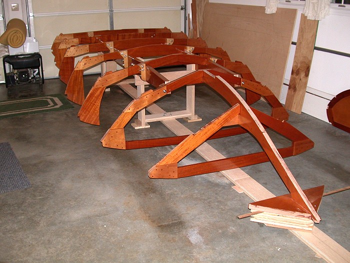
The building form and strong back are complete and the motor
stringers and frames are mounted. I was concerned about twist
and/or distortion in the building form. Therefore, I used two
layers of ¾ inch Baltic birch plywood in constructing
the building form. I took considerable time leveling the form
before anchoring it on my wife's side of the garage. I
told her it would only be there for a couple of months - -
turned out a couple of years.
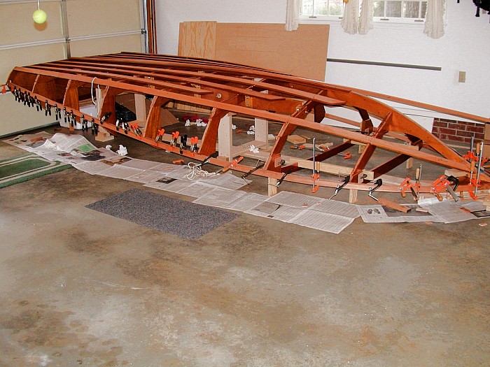
The keel, chine, sheer clamps and battens are mounted. I
broke one sheer clamp during installation. Therefore, I used
laminated sheer clamps glued with epoxy as shown in the
photo. All surfaces that will be exposed received three coats
of marine varnish. All surfaces that mate with another
surface remained raw.
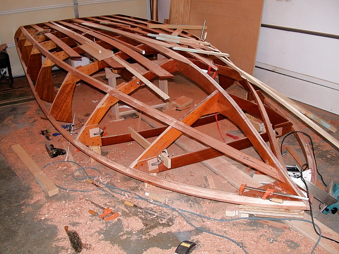
Fairing all of the surfaces per the instructions was very
tedious and time consuming. I used hand planes, power plane
(be careful), files, conventional sanding blocks and custom
made sanding surfaces.
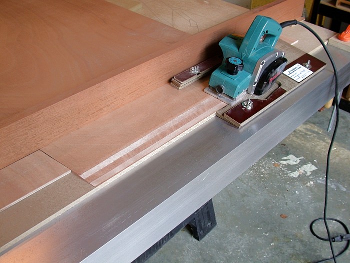
I elected to use scarf joints (8:1 ratio) to obtain the
desired length of Okume plywood. I purchased a John Henry
scarf attachment for my Makita power planer. I used a large
aluminum angle to insure a true surface. Later the angle was
cut up and used for motor and V-drive mounts.
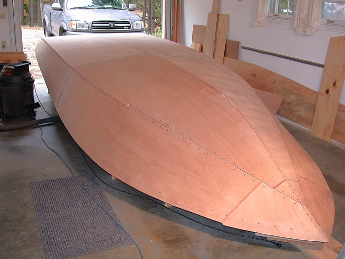
Please note the scarf joints in the bottom and side plywood.
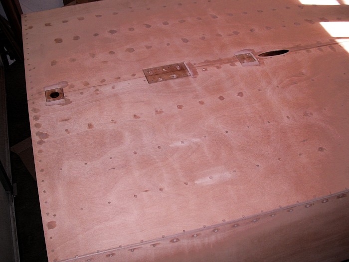
Locations were flattened for the rudder shaft/bearing
fitting, main strut, and whip strut. Holes for the rudder
shaft and propeller shaft were drilled. Practice drilling the
propeller shaft hole on the mockup was invaluable for the
real thing.
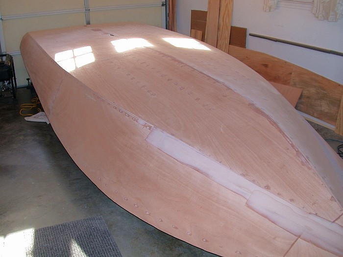
I used a little epoxy filler to assist in the fairing along
the chine from about frame five forward.
My preferred sequence in fiberglasing is to first apply a
liberal coat of epoxy to the raw surface and then sand smooth
prior to installing the fiberglass cloth.
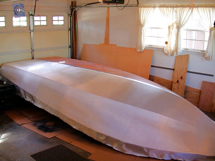
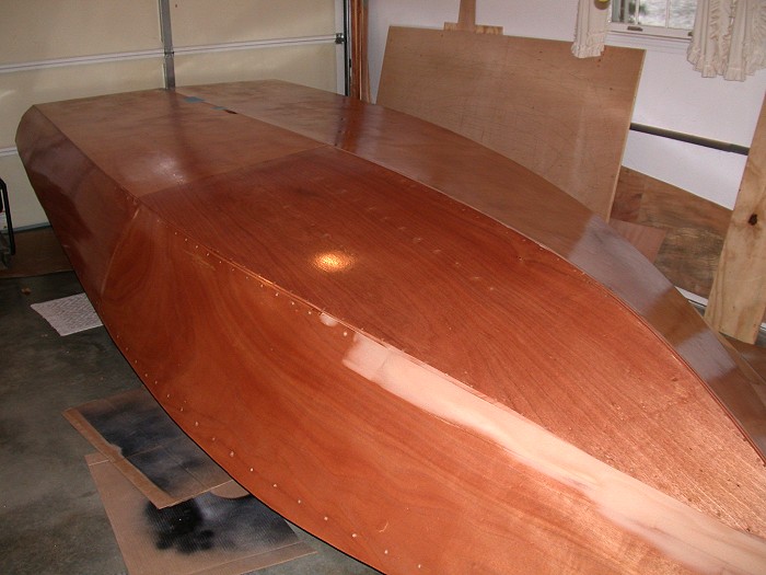
I fiberglassed one half of the bottom/side at a time using
three coats of epoxy to obtain a smooth surface above the
glass.
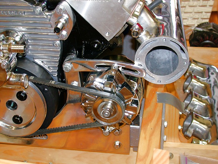
Back to the mockup. Interference problem is obvious between
the water-cooled exhaust manifold and the generator/generator
bracket.
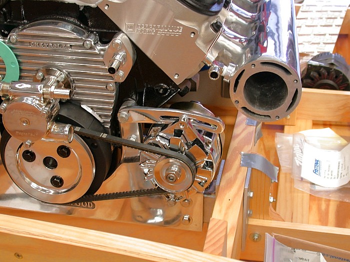
The solution we chose was to reverse the manifolds. The
individual exhaust ports on the big block are "D"
shaped so that was not an issue. However, a considerable
amount of metal (aluminum) was carefully removed from the
manifolds so they would clear the spark plugs.