Tubby Tug by Bill Hodgdon, Strafford, New Hampshire
June 25, 2009This recently completed project (Launched Aug 1, 2008) involves a modified Tubby Tug, which is different from the standard version in that it is electric power, has a folding top, and a fantail stern.
I have built about a dozen boats, the first being a Glen-L Squirt in 1960 with my Dad. I was also a draftsman and later an engineer before I retired. I only point this out because the faintail stern modification I did, involved complex full-size lofting that I do not recommend to anyone without the experience to do so (not recommended for new boatbuilders). That said...here's my story.
My wife wanted a small electric boat to go out on the lake early in the morning as the sun rose, to watch the Loons, and just quietly look at the peaceful morning. When she asked me to build her one, I took her to the Glen-L site and asked her which of the special purpose electric boats she wanted me to build. Unexpectedly, the Tubby tug was also in that category, and she said for sure, that was the one she wanted. Unfortunately, we have a low bridge (42" clearance), so the top would need to be retractable, somehow (leaving the top off was not an option). My 88 year old Dad spent lots of time helping aboard the local harbor tugs as boy, and we both thought that even though it would make the job much more difficult, the transom should be a traditional fantail stern. (I think I spent as much time on the fantail stern as on the rest of the boat, all considered). Since there are many excellent articles on building the Tubby Tug, I will just focus on these different modified areas of my Wife's Tubby Tug.
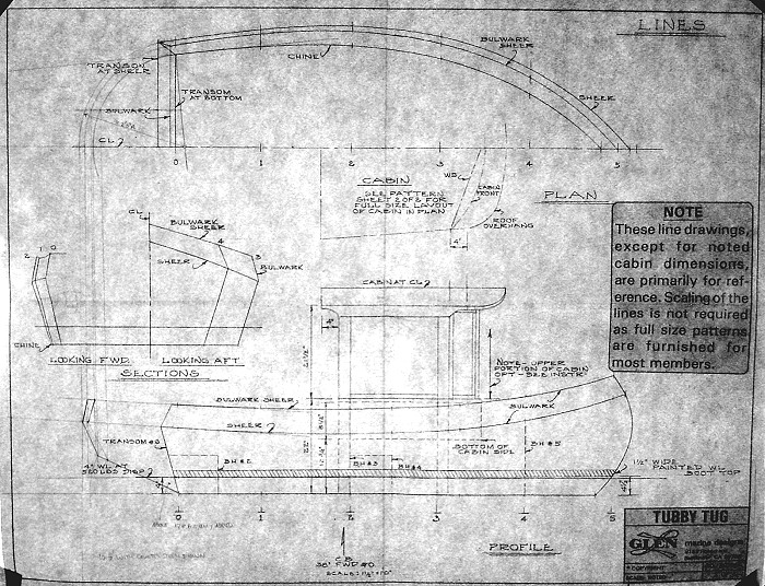
A sketch on the study plans showed that the fantail stern was
possible, and would not look unreasonable, so I proceeded to
design a new stern for the Tubby Tug. This was done full-size
on some of the plywood that would become the hull (and so
there are no remaining plans for the design change). A quick
check of moments showed that the two AGM batteries mounted at
the front seat area would effectively offset the approximate
weight of the new stern, taking into account the minor
increase in displacement. The fantail was developed to be
circular from directly overhead, with the hull sides and
bulwarks being conical. Note that the circular appearing
rings used to form the fantail are actually not exactly
circular, since they are not in the horizontal plane. There
is nothing truly circular in any of the framework for the
transom.
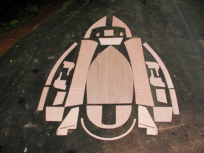
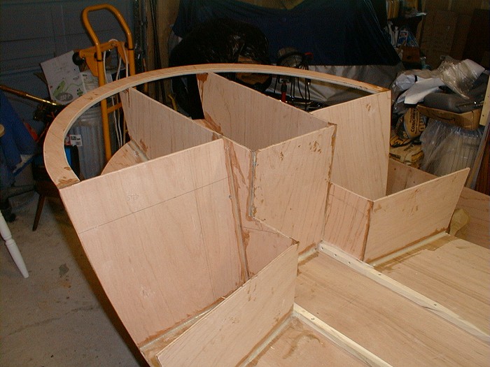
So, the first set of parts were cut out from the plans and
the lofting. The hull sides were scarf joined in lieu of
using a butt block. It wasn't until after I took this
picture that I realized I had made a little space man out of
the parts...totally by accident. You can see many of the
parts that form the fantail stern in this shot.
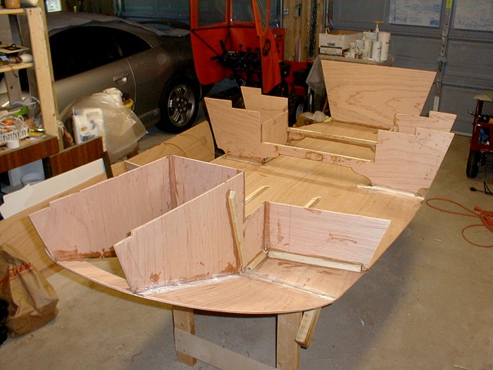
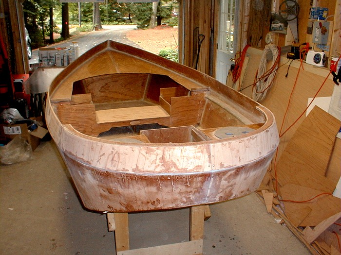
Here we have begun construction. The inclined bottom of the
fantail stern begins where the true transom should be
located. The rear seat supports are angled slightly to
provide a better drainage to the center of the rear seat
area, where a bilge pump will be located. (Length and side
angle requires adjustment with this change). The rectangular
center well for the trolling motor has a vertical forward
face to allow retraction of the trolling motor for trailering
or beaching. The motor and propeller will completely retract
above the bottom of the boat. The front seat has been cut
down for a cushioned swivel chair, and the forward front seat
support has been moved forward to allow room for the AGM
batteries to sit in a fore and aft orientation. This requires
changing the forward seat supports to fit the hull in the new
location. The front seat will swivel 360 degrees when
installed, making it easy to get in the pilot house.
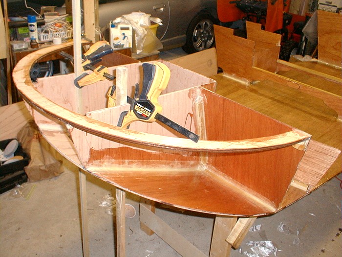
The lower ring has been attached to the normal Tubby Tug
modified transom and will define the joint location between
the hull and bulwark. The normal transom portions are
actually angled back per plan, although they do look vertical
here.
Here's another view for reference. The two stiffeners
attached to the bottom are temporary.
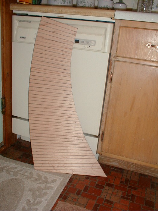
Here is one-half of the fantail hull panel (they are butt
block joined on centerline). The 5-ply 1/4" plywood was
too stiff to bend around the curve without breaking, so 1/8:
cuts were made approx 3/4" apart along the panel. Note
that since this is a conical panel, the cuts are not
parallel. (After installation, the grooves were filled with
epoxy paste and then the panel was epoxy fiberglassed over.)
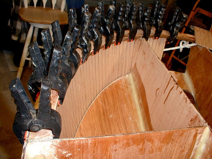
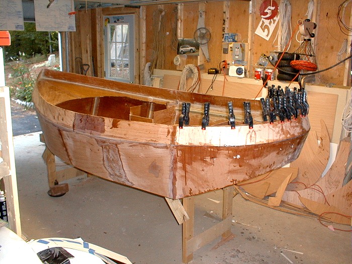
Here is the panel, clamped in place for a trial fit.
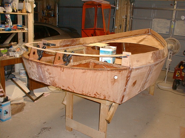
The fantail stern hull panels are installed and the ring that
defines the top of the fantail bulwarks has been installed.
You can see the white outlet for the bilge pump in this view.
The hull panel overlaps the bottom here, and it has not been
trimmed yet.
Now we have installed the fantail bulwarks as well. These
panels also required relief cuts to prevent breakage.
Well, now it's beginning to look like a fantail stern!
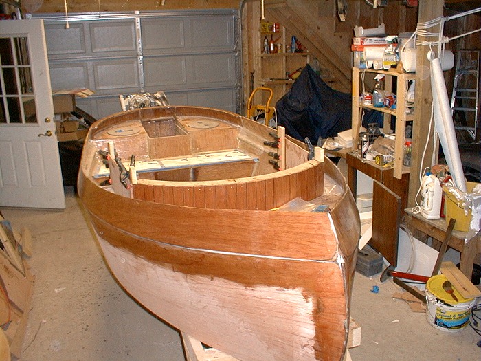
This is a trial fitting of the cabin, note the cut off posts
where gussets will be added for the cabin top pivots. The
posts are all aligned fore and aft, not aligned with the
cabin sides. Tapered shims were used for proper alignment.
This is so there will be no binding when the roof pivots
down.