Shop Talk: Small Boat Electrical System
by Terry McIntyre
I installed the electrical system before I put the deck on the boat. While I suppose it is theoretically possible to do it afterward, it would be much more difficult, particularly in a boat as small as a Squirt. The wiring should be installed with enough slack that you can get it loose if you need to fix something later, but tight enough that it doesn't flap around when the boat bounces. My wiring is supported by screw-in tie-wraps about every 8 inches, with one or two smaller tie wraps between them to keep the wiring in tight bundles. Wherever a screw pierces the interior hull encapsulation, it was installed in a healthy gob of silicone caulk.
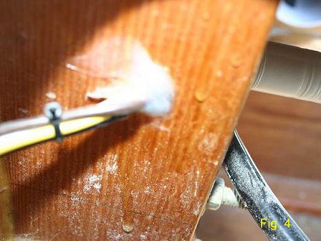
One worry in a small boat electrical installation is that vibration can chafe the wire insulation, leading to a short. This can occur when there is a sharp edge of any structure that is in contact with a wire; for example where a wire bundle passes through a frame. One way to avoid this is to immobilize the wire relative to the structure by filling the hole completely with silicone caulk. This is shown in Figure 4.
The subject of batteries could be another article the length of this or longer, but a couple of notes are in order. Batteries come in two different types, starting batteries, optimized for high currents for short periods of time, and deep cycle batteries, for lower currents for long periods of time. Runabouts that have only one battery should have either a starting battery or a combined deep cycle/starting battery that is offered by some manufacturers. Any boat that will be away from the dock with major electrical loads while the engine is not running should have two batteries, one of each type, connected appropriately so that the batteries can be charged simultaneously, but discharged independently, and either battery used to start the engine, using an off-1-both-2 switch for example. I seriously considered a two battery installation for my Squirt, but there was just not enough space. The number one reason boats need to be towed in is "the engine won't start", and the number one reason for that is "discharged battery". If you have room for two batteries, install 2 batteries!
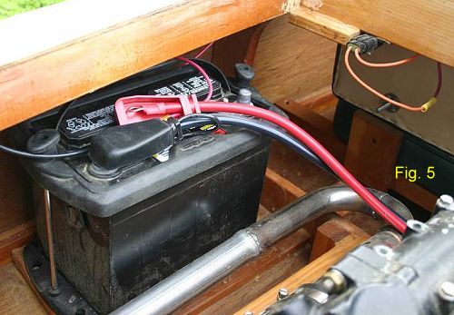
Figure 5 shows my battery installation and its connections, located on the port side front of the engine bay. ABYC does not require that batteries be boxed, but it does require that they be fixed in place. I chose a hold-down system. If you put your battery in a box, make sure that it can be securely fixed to the boat structure. This may sound obvious, but make sure that the battery can be removed for replacement should the need arise (it will!)
In the photo, the negative cables are connected to the battery, and the positive are not yet landed so that you can see the connections. The heavy gauge red and black wires are the positive and negative starting cables to the starter solenoid and engine block ground, respectively. The smaller wires are the main feeds to the "house" electrical system. Both the battery terminals are covered with plastic cable caps to preclude the possibility of something falling on the battery and causing a short.
The black negative splits and is routed to both the forward and aft negative busses. The forward wires go athwartships just behind the cockpit - you can also see the fuse holder (orange wires) that is cut into the main positive supply line. This location is easy to reach if I ever have to change the fuse.
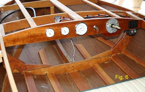
Figure 6 shows the dash with all the gauges and switches installed. The speedometer is in the center, with the fuel gauge and voltmeter to port. The main on-off ignition switch is between the speedometer and the helm. Starboard of the helm are the control switches, and the start/stop switches (my engine is a 2-stroke) for the engine. Also visible in this picture on the #2 frame deck beam is the positive light bus - a single wire from the light switch breaks at this point into five separate circuits to the running lights and dash lights.
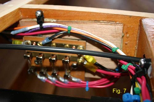
Figure 7 shows the fuse/distribution panel that is also located behind the dash on deck frame #2. The panel needs to be located where it accessible so that a fuse can be replaced, if necessary. The main positive supply is the larger red wire that comes in from the right, terminating at the brass bus bar at the top of the fuses. The smaller red wires at the bottom go to the individual device switches in the dashboard. This panel also includes the forward negative bus at the top of the panel. (The heavy black tube running across the middle of the picture is the speedometer pressure hose from the pitot tube at the transom.)
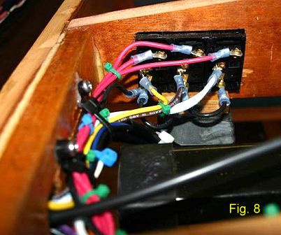
Figure 8 looks at the back of the control switches behind the dash. The red wires at the top are the individual circuit supplies from the fuse panel. The wires at the mid plane are the feeds to the blower (yellow), bilge pump (brown), and lights (white). The red wires are always "hot" but the circuit feeds are only powered when the switch is on - that's why the color coding changes at this point. The black wires at the bottom are negatives for all the switches - I chose switches that are lighted when the circuit is "on", so a connection to the negative bus is necessary.
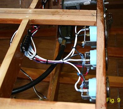
Finally, Figure 9 is a close up of the wiring to the gauges. Here again you can see the lighting bus, and particularly the downward loop of wiring between the dash and the gauges themselves. This is good wiring practice, as any condensation will tend to drip off the wires at the low point instead of running down to a connector, where water could lead to corrosion in the connector or in the wire itself.
In summary, wiring a runabout requires some up-front design, understanding of requirements, and care in installation. This is one area where you should not scrimp, as an incorrectly designed or installed system can potentially lead to a fire on board, which is something that you definitely do not want to have. With a little time and patience, however, doing it right is well within the capabilities of the amateur boat builder, and will result in a robust, reliable, and safe electrical system. I hope that my experiences will be helpful to others.