I Fell in Love (cont'd)
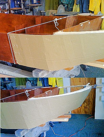 I took a large sheet of cardboard, attached
to the aft section of hull at the butt joint, and bent the
cardboard around the "U". It is well to run the
cardboard past center line. By adjusting up and down the
contact on the "U", a proper slope of the upper
fantail is established. It cannot be too sharp as the
material must bend around the lower corner of the transom. I
did remove a tapered piece of the hull bottom, about 1/4 by 4
inches at the transom. This helped a great deal in easing the
curve.
I took a large sheet of cardboard, attached
to the aft section of hull at the butt joint, and bent the
cardboard around the "U". It is well to run the
cardboard past center line. By adjusting up and down the
contact on the "U", a proper slope of the upper
fantail is established. It cannot be too sharp as the
material must bend around the lower corner of the transom. I
did remove a tapered piece of the hull bottom, about 1/4 by 4
inches at the transom. This helped a great deal in easing the
curve.
I established the lower line of the fantail by placing the
inner cut out piece of the "U" inside the cardboard
against the lower edge of the transom allowing it to fall
against the slope of the cardboard to establish the line on
the cardboard for the lower part of the fantail. The
cardboard pattern was trimmed, leaving about 1 1/2 inch extra
on all edges for final trim of the plywood once it is in
place. A left and a right pair were cut from 1/4 inch
plywood. It is best to layout the kerf lines to make them
even. About 3/4 in. at the top to about 1/2 in. at the
bottom. These lines should be perpendicular to the top curve.
You are making a cone shape, not a cylinder. Be sure to use a
sharp plywood blade and support the plywood on a flat table
as you cut the kerfs.
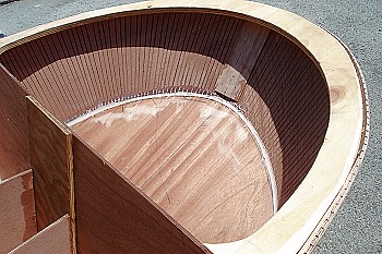 The aft section of hull was removed from the
butt block (that is why it was screwed in place) and the new
section of hull/fantail was set in place, stitched with
copper wire to the transom, and bent around the
"U". It took two men, some clamps and a rope to
bring the curve into place. The bottom of the fantail is laid
out using the inner cut-out of the "U" as a
pattern. All is stitched and glued together. Be sure to fill
the kerf cuts with epoxy paste or fairing material and
glassed over. After coving and fiber glassing the seams
inside, the extra width of the fantail sections can be
trimmed.
The aft section of hull was removed from the
butt block (that is why it was screwed in place) and the new
section of hull/fantail was set in place, stitched with
copper wire to the transom, and bent around the
"U". It took two men, some clamps and a rope to
bring the curve into place. The bottom of the fantail is laid
out using the inner cut-out of the "U" as a
pattern. All is stitched and glued together. Be sure to fill
the kerf cuts with epoxy paste or fairing material and
glassed over. After coving and fiber glassing the seams
inside, the extra width of the fantail sections can be
trimmed.
I used a pneumatic stapler (1/4 by 7/8) to join much of the
plywood. The staples can be removed or ground off. It makes
for a very fast way to clamp. I used 5 minute epoxy on many
of the joints, spread the epoxy and popped in a few staples.
All the cut out pieces were first coated with penetrating
epoxy. This made gluing, coving, fairing, and painting much
easier. I used carbon fiber fabric and epoxy on all joints.
More expensive than fiberglass, but easier to sand, and no
itch!
The fantail bulwark is laid out much the same way as the
fantail, only this time you have two "U's" to
bend to. The upper "U" is cut from the well used
"inner cutout". The "U" is blocked at the
correct height and the cardboard pattern is bent around the
two "U's" starting from the butt joint in the
bulwark. Again, use your eye to establish a pleasing
line.
I kept a log of my time and found that I could not make as
good time as Kevin Brown, about the same with two men
working as with his one. However, as I studied my log, I
realized that it took more time to build the fantail than to
build the rest of the hull. A great deal of thinking time
goes into custom work.
I built the pilot house with a forward angle to the windows.
I used the Tubby Tug basic plans, but of course all the
dimensions and angles were different. Much trial and error
was involved. (Emphasis on the "error")
I added a vertical block at the aft end of the fore deck at
the pilot house, then opened the bulkhead at that point to
add a drain scupper. The forward bulkhead was cut open for my
big feet, and a ceiling was added above to make a water tight
compartment which I use as an anchor chain locker.
The rope molding in the bulwark looks good, but is VERY
labor intensive!
 The steering mechanics was the most time
consuming part of this project. I tried 4 different systems
before I got the steering to work. In the new fantail hull, I
added two fore and aft bulk heads 6 inches apart. This is the
width needed to drop in (if I ever wanted to) a small gas
outboard motor through a cut out in the bottom. I made a 2
inch cut out between the bulkheads so the electric trolling
motor could swing up through the fan tail. This all worked
well and good, but I could not make a mechanical connection
that both steered and swung. However, this would work if a
remote steering system was used like in Bill Hodgdon's
design.
The steering mechanics was the most time
consuming part of this project. I tried 4 different systems
before I got the steering to work. In the new fantail hull, I
added two fore and aft bulk heads 6 inches apart. This is the
width needed to drop in (if I ever wanted to) a small gas
outboard motor through a cut out in the bottom. I made a 2
inch cut out between the bulkheads so the electric trolling
motor could swing up through the fan tail. This all worked
well and good, but I could not make a mechanical connection
that both steered and swung. However, this would work if a
remote steering system was used like in Bill Hodgdon's
design.
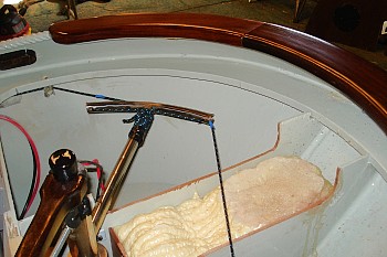
I finally created a cavity the size of the motor in the
bottom of the fan tail. I built a telescoping system for the
vertical tube of the motor, thus eliminating the swing up
action. Then added a quadrant to the telescoping system. The
quadrant is adjusted with a set screw. Now the set screw can
be eased off and the motor can be lifted into the cavity, and
locked in place for trailering. Steering is by a traditional
drum and cable on the quadrant with a wooden steering wheel
in the pilot house.
When I started building HERCULES my wife asked me why I
wanted to build yet again another boat, as I have two
already. Simple answer: "It puts a grin on my
face."
