Rigging Small Sailboats
Chapter 7
.....installing fittings to the hull
Page 2Chainplates can be made of any strong metal as long as it is non-corrosive. However, it is common to purchase ready made chainplates which are usually made from stainless steel strap with holes usually drilled in each end. If in doubt about which size chainplate to use, always pick one that is larger and as long as practicable. Always bolt the chainplate in position with at least two bolts per unit. Be sure to let the top end of the chainplate extend far enough above the deck or cabin top to allow the shrouds to be attached. Where chainplates protrude through the deck or cabin top, the hole should be sealed in a water proof mastic. Special covers are available which match the ready-made chainplates to cover the hole and "dress up" the area where the chainplates pass through.
If in doubt about the location of the chainplates, remember that they are located as far outboard as possible, as far as strengthening the mast is concerned. They must not, however, interfere with sail handling; especially when a jib is used. Also, if a single shroud on each side is used, the chainplates are usually located a little aft of the mast. When upper and lower shrouds are used, the chainplate for the upper shroud is usually directly to the side of the mast. The chainplates for the lower shrouds are then located a slight distance forward or aft of this chainplate. When more than one chainplate is required per side, they should be separated by a distance of at least several inches in order to transfer the strains to the hull.
INSTALLING DECK FITTINGS
Deck fittings such as blocks, cleats, winches, tracks, and related items should be installed with bolts or long screws as previously noted. Fastenings are usually not provided with the deck fittings when purchased because the lengths will vary from boat to boat.
In installing fittings such as for the mainsheet, it is advisable to mock-up the arrangement before fastening anything permanently in position, especially if you are not familiar with the configuration, or are figuring out your own arrangement. Tape the fittings in position and check to see that all fittings are in the proper position and plane of reference for smooth operation. It would be mighty embarrassing to find that a cam cleat, for example, was fastened in backwards! While the designer will probably note the positions of the various fittings, the best locations for the fittings can be determined. Also check the position of the various jam cleats which will be used to belay the various sheets and halyards. Obviously these jam cleats must have a "fair lead" to the line and be in a position so the line will stay secure. Always locate jam cleats so the pull of the line is at right angles to the line of the fastenings; not in line with them which will tend to pull the cleat out.
If your rig has a jib, care must be taken in locating the jib sheet lead points; the position where the lines controlling the trim of the jib intersects with the hull. Designers use a formula for determining these positions and it has been noted previously and in Fig. 5-16. The builder can also use this formula, but because conditions of use, the sails, and boats in general vary, the best method for determining jib sheet leads is by actually sailing the boat and pinpointing the lead position while using the jib. Admittedly, this may seem tedious and inconvenient, but on the smaller boats with jibs up to about 50 square feet, it is really not too much effort.
With either method, once the correct point is determined, a fixed or adjustable lead fitting can be installed. On small boats, a fixed lead need consist of nothing more than a fairlead fastened to the deck on each side for each jib sheet. On larger boats, or where more efficiency is desired, a track can be used on either side with a sliding fairlead. This method allows for variable trimming of the sheet when underway, which is desirable when the conditions of sailing change. This track for the jib would be located so the mid-length of the track is positioned at the point found to be most efficient. The track used for the jib is usually at least 12" long. On larger boats that use a Genoa, a separate track is provided for this sail, each side of the boat. The lead point for the Genoa can be found by the trial-and-error method, but because of the size of the sail, this is difficult, to say the least. For this reason, it is better to use the formula provided to determine the lead point for the Genoa, and then use a longer length of track for the fairlead slide so that variations are possible. In most cases the Genoa track is located fairly parallel along the sheer rail as far outboard as practical. Track stops must be provided for all jib and Genoa tracks at the ends so the slides will not come off when underway.
When winches are required for handling sheets and halyards, their position must be carefully determined. Halyard winches are generally fastened to the mast, but are really not considered necessary equipment on the size boats being considered here. This leaves winches which are used for the jib or Genoa sheets. Here again the position of the winches will usually be noted by the designer, but as stated previously, this will be an approximation, and the exact position for the winches is best determined in use once the sheet lead points are known, or at least mocked-up.
In locating winches, several things must be considered. First, the winch must be near at hand and convenient to use. If it has a handle, clearance must be allowed for a full circle swing. Winches may be located on deck, but it is common to raise them up on blocking in order to clear cockpit coamings. If the winch is blocked up, this blocking should be angled so the lead of the sheet from the track is fairly horizontal to the winch. A cleat is always used to secure the sheet after taking turns around the winch. These cleats are preferably in a horizontal plane with the winch as well.
When installing "outboard" rudders on the transom, gudgeons and pintles, as described in the previous chapter, are used. Sometimes inboard rudders are used, and these are usually detailed on the plans by the designer. With "outboard" rudders, most commonly the pintles are bolted to the rudder. The gudgeons are then screwed or bolted to the transom. Most boats use a set of two each, and these should be spaced as far apart as possible to distribute the strain on the rudder. Install a rudder stop if there appears to be any tendency for the rudder to float up and out of the gudgeons. Any number of types of rudder stops are available, some of which may be integral with the rudder fittings. Another method which can be used but is not very seaman-like is to bend the pintles with pliers so they fit tighter in the gudgeons.
|
|
|
|
|
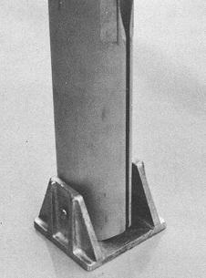
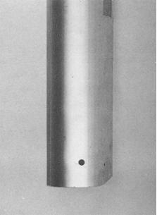
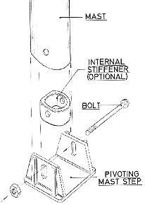
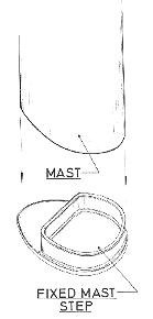
FIG. 7-2 through 7-5 - Two types of mast steps are shown for use with aluminum spars. The first pivots; the aft corner of the mast at the base is radiused to allow clearance when pivoting. The exploded view shows an internal stiffener used on light masts to provide bearing for the bolt. The second type of step is fixed to the deck and the mast sets onto it. It is held in position by the stays. |
|
Installing the mast step may not require any fittings if the mast is to be stepped through the deck and provisions have been made in the hull structure. However, with masts that are to be stepped on the deck or cabin top, a means of securing the mast is required, and this is usually by the mast step fitting such as shown by Figs. 7-2, 7-4, and 7-5. As noted previously, several types of steps are available. Depending on the design, reinforcing below the mast step may be required, such as a mast stanchion or large deck beam. The reason for this extra support is that the mast is in direct compression onto the boat and the considerable strain must be transferred throughout as large an area of the structure as possible. So it is important that the mast step be located directly over these strength members and rigidly mounted. Mast steps are preferably through bolted in any case.
The next WebLetter will include chapter 8 ...outfitting spars.