On the Mark: Frame construction
Continued...
Layout area/work table
You will spend a lot of time working on the plans and frames. If possible, use an elevated work table as I did. This saves a lot of wear and tear on the back and knees. This is practical for boats up to ~ 20-24 feet. Above that you will need to work on the floor as you will exceed an arm's reach and would need to climb up on it anyway. I used a 3/4" thick 4'x8' sheet of melamine coated particle board (~$35) propped up on 2 barrels (saw horses would work as well).
The melamine provides a nice smooth surface to
trace onto. The lines show up clearly and have lots of contrast. The smooth
surface helps in creating good tracings on the reverse side of the plans.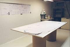
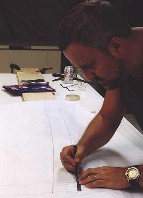
Tracing on Table
The table and the back of the plans need to have the frame outlines traced onto them. This is done by laying the plans on the table with 2 layers of carbon paper sandwiched in between. 1 layer faces up to mark the back of the plans and the other faces down to mark the table. Be sure to tape the plans down prior to tracing. You can either use drafting tape (hard to find low tack masking tape) or other low tack / easy to remove tape (I like the 3M blue masking tape). I did the tracing with a 0.5 mm mechanical pencil with a HB lead.
Unless you are far steadier than I am (younger and don't drink coffee), the tracings will be greatly improved if you use a straight edge or large French curve to guide your pencil. The curves are not very tight and if you use a straight edge (I liked using the back edge of a hacksaw blade as shown in the photo), the piecewise linear lines (each section 1-2" long) makes a very good and accurate representation of the frame curves. The hacksaw blade is light and the teeth provide just enough friction to keep it from slipping accidentally as you trace.
When tracing on the table, be sure to allow room for the other half of each frame at assembly time.
The melamine is on both sides of the board. I flipped it over half way through to have a fresh work surface and eliminate confusing lines.
One pack of carbon paper (yes they still sell it at office supply stores) will last the entire project and then some. Glen-L has large size carbon paper, so you don't have to handle the individual sheets (Transfer paper). When laying out the sheets don't worry if they overlap, 1 extra layer won't hurt.
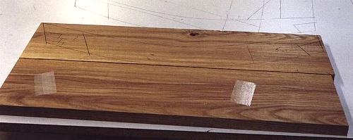
Transferring frame pieces to wood
 |
| Click to enlarge |
Mark each set of frame outlines with a circle or other indication of the frame you are about to trace. Check off each section on the plans as you trace it. Since you need to stop and reposition the plans for each board, it is easy to get confused and trace the wrong item. You don't want to be assembling the sides of frame 4 onto the rest of frame 5 (this would only happen if frame 4 is already complete as well).
Clamp your longer pieces down (such as carlings) prior to tracing. Lay the carbon paper on the wood and tape the plans down to the piece of wood. Prior to tracing, run your finger around the plan lines to make sure nothing has shifted and all of the plan for that piece lands on the wood. Of course if it slips, the last part to be traced is the part not on the wood.
Once again use an edge guide. This tracing IS THE SHAPE of the hull. If you are not accurate now and in the next steps, you will have a LOT of fairing to do later. At this point, we want the lines transferred with <1/16" accuracy.
When I talk about striving for high levels of accuracy at this stage, don't let it scare you off, but instead look to the points mentioned as pointers to what is important for later stages. For example, the inside of the frame edges has nothing to do with the hull shape. If you want to leave it rough, go ahead (but please figure out a way to cover it up).
Cutting and sanding
 |
|
Click to
enlarge |
If you have access to a band saw, sawing these pieces is relatively easy. Use a 1/2" 3-4 TPI (tooth per inch) skip tooth blade. The stacked wood is then fed through. The 1/2" blade evens out the curves and provides a fair cut. The skip tooth blade clears out he sawdust well and leaves a clean enough finish that it will sand easily.
While the pairs are still together, sand the edges. You want a matched set and this is the way to do it. Use a large belt sander or drum sander (for the inside curves). The outside edges must be square. If you tip the piece, the 2 parts will no longer be identical. It is much easier to keep the piece square with both parts held together, due to the wider working area. Do not sand so far that you remove the lines. Sand to the lines, not through them.
Make use of the knotty or curved grain pieces for the frames. Arrange the pattern so that the wood grain flows with the curves for greatest strength. I used all #1 Common wood for the frames. Since the pieces are not all that big, you can easily work around the knots. At the mill where I buy my wood, the savings over select is ~40%. Save your clear straight pieces for the battens, chines and sheers. In addition, the #1C wood may have a clear edge which is suitable for battens if ripped off prior to cutting to length.
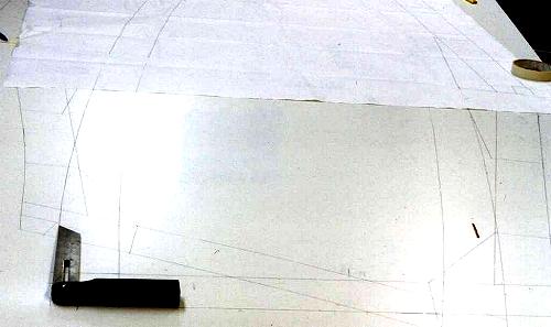 |
| Bevel gauge on plans - Click to enlarge |
If you have access to a power miter box (chop saw), radial arm saw or table saw, the angled ends of the corners may be cut there with some improvement in accuracy. Transfer the angle with a bevel gauge as shown. The enlarged photo also shows the plans flipped on the table, ready for frame alignment.
Prior to assembly, sand the faces as well to remove the planer marks. 80 grit is fine and provides a nice "tooth" for the epoxy to hold into.