Inboard Motor Installations
Chapter 6 - V-drives
Continued
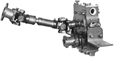 Fig. 4-5 - This V-drive unit is basically a transfer case that changes the direction of the engine's propulsion. Note the double universal joints and torque tube assembly. This unit does not have a built in angle. (Courtesy of Walter Machine Co., Jersey City, NJ.) |
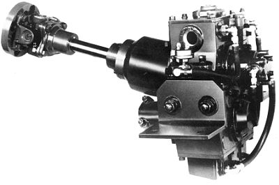 Fig. 4-6 - This V-drive unit has a built-in angle. The second universal joint is not visible, as it is built into the V-drive. The opening in the side is for connecting the water cooling system. (Courtesy of Walter Machine Co., Jersey City, NJ.) |
Various types of V-drive units are available. The basic V-drive is merely a transfer case as noted previously (see Fig. 4-5 above). When these are used, a marine transmission is usually connected to the engine to provide forward, neutral, and reverse control. In other cases, V-drives are available which include an integral marine transmission (see Fig. 4-7). The transmission in the V-drive may be of the forward-neutral-reverse type, or in some cases where reverse gear is not used, such as in the smaller runabouts and competition boats, the V-drive may be the so-called "in-and-out" type having just a neutral and forward position (see Fig. 4-9) V-drives are available which are remotely located from the engine, or which are close-coupled to the engine or marine transmission, which is in turn, mounted to the engine (see Fig. 4-10 and Fig. 4-11 below). Such units are quite compact and are ideal where space is at a premium. If a reduction gear or overdrive is necessary, this can usually be incorporated in the V-drive instead of in the marine transmission. Another variation available with V-drives is the split case type (see Fig. 4-12). This allows relatively quick changes to be made to the gears, thereby changing the ratio. Such V-drives are often used on high speed boats that will be used for a variety of conditions, such as water skiing and racing, or where weather and sea conditions make the gear change feature desirable for efficiency.
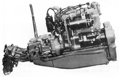 Fig. 4-10 - This marine
engine features a direct close-coupled V-drive with marine transmission. Such a
unit saves valuable space. (Courtesy of Medalist-Universal Motors, Oshkosh,
WI)
Fig. 4-10 - This marine
engine features a direct close-coupled V-drive with marine transmission. Such a
unit saves valuable space. (Courtesy of Medalist-Universal Motors, Oshkosh,
WI)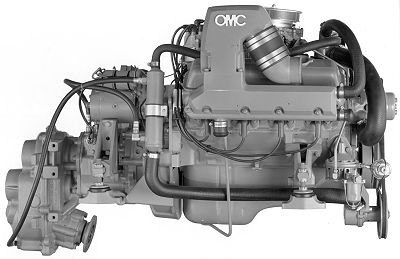 Fig. 4-11 - Another
example of a marine engine coupled directly with a V-drive. In this case, the
engine is a large displacement V-8. Note the oil cooling hose from the V-drive
to the oil cooler, the water cooling hose connecting both ends of the oil
cooler to the engine. (Courtesy of OMC, Waukegan, IL)
Fig. 4-11 - Another
example of a marine engine coupled directly with a V-drive. In this case, the
engine is a large displacement V-8. Note the oil cooling hose from the V-drive
to the oil cooler, the water cooling hose connecting both ends of the oil
cooler to the engine. (Courtesy of OMC, Waukegan, IL)
On V-drives which are located remotely from the engine, the propeller thrust must be taken by the V-drive if it has built-in thrust bearings. If not, a separate thrust bearing and housing must be provided aft of the V-drive (see Fig. 4-14). Most V-drives have built-in shaft angularity at some fixed degree, usually 10 or 12 degrees. V-drives may sometimes be air cooled, however, most modern units are water cooled. Many V-drives tend to be noisy in operation, however, this varies with the unit and the type of gears used.
A common question with prospective amateur boatbuilders is which is the cheapest power system; the conventional centrally located motor with straight shaft, the V-drive with stern mounted inboard, the stern mounted inboard using a sterndrive, or the stern mounted motor using a jet drive? This is a difficult question to answer because there are so many variables, assuming that the boat could take any or all of these systems. Much depends on if the individual has a motor and will convert it himself, what type of shifting arrangement he is willing to settle for, how much of the installation work he will do himself, and on the prices for the various items of equipment. With V-drives alone there is a wide variety of units which results in a wide range of prices. Consequently, each situation must be checked through with all the possible alternatives to arrive at the lowest cost for a given type of power installation.
INSTALLING THE V-drive
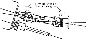
Plate 8 - The angularity difference between the V-drive and the engine must be equally "split" between the universal joints in the torque tube installation as shown by the dimensional tolerance. If not, wear will be concentrated on one joint, causing it to fail prematurely. |
Installing a motor with a separate V-drive is simpler than installing a conventional centrally located motor and transmission. The reason, to a great extent, is the fact that close alignment is not required for the engine. Often the motor is separated from the V-drive by some distance. For this reason a double universal joint with torque tube is usually used to connect the motor to the V-drive (see Fig. 4-15 below). It must be understood that two universal joints are required. A single universal will take up differences in angularity on one plane only. Because there are two angles, one for the V-drive and one for the motor crankshaft centerline, compensation for the angularity in both planes requires the use of two universal joints. Best practice calls for the angularity difference between the motor and V-drive to be equally taken by the universal joints. In other words, the angle is split 50/50 between the two universal joints. Putting all the action on one will not only cause excessive wear, but may also set up excessive vibration (see Plate #8 above).
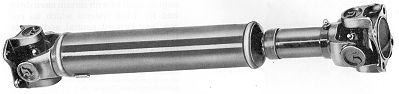
Fig. 4-15 - A typical torque tube with universal
assemblies used to connect the engine to the V-drive. The torque tube
compensates for minor angularity differences between the engine and
V-drive.
With engines that have the V-drive coupled to the engine or to the transmission directly, the use of the torque tube and double universals is not required. Such engines are installed similarly to the centrally located inboard with straight shaft, which will be covered later. Otherwise, the V-drive is mounted to the motor stringers or other structural hull members, using mounts or a "cage" provided with the unit, or purchased separately (see Fig. 4-14). Alignment to the propeller shaft must be accurate. Connection to the propeller shaft may be made by either a flange coupling or a split sleeve coupling. Various couplings are discussed in Chapter 7. If the flange coupling is used, alignment of the V-drive flange coupling to the shaft flange coupling is done the same way as with the standard straight shaft centrally located inboard motor described in Chapter 8. If a split sleeve coupling is used, the coupling connects to the propeller shaft and to the stub shaft on the V-drive. Alignment is quite simple. With the coupling on the propeller shaft, the connection is made to the V-drive. When the propeller shaft will spin freely when connected, alignment is true.
A recommended safety option for V-drive assemblies is the addition of a guard over the torque tube. In high-speed operation, universal joints have been known to fail. The whipping shaft can cause severe damage to the hull as well as injury to crew members. This guard may simply be a ring protector over the torque tube shaft. With some V-drives, a power takeoff vee-belt pulley can be used on the V-drive upper shaft to drive certain accessories such as generators and alternators.