
.....masts and booms
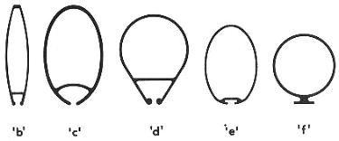
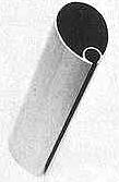 FIG. 3-1-Some
typical aluminum mast sections. Sections 'a', 'b', 'c',
and 'd' have built-in grooves for the bolt rope of the sail. Sections
'e' and 'f' are made for sails with track slides, with
'e' using and internal slide and 'f' using an external slide.
All these sections are made by extruding the metal. Ordinary aluminum tubing is
also used for spars in some cases, where the strength is sufficient. Most of
these sections could be used for the boom also, if of the appropriate size and
shape. FIG. 3-1-Some
typical aluminum mast sections. Sections 'a', 'b', 'c',
and 'd' have built-in grooves for the bolt rope of the sail. Sections
'e' and 'f' are made for sails with track slides, with
'e' using and internal slide and 'f' using an external slide.
All these sections are made by extruding the metal. Ordinary aluminum tubing is
also used for spars in some cases, where the strength is sufficient. Most of
these sections could be used for the boom also, if of the appropriate size and
shape. |
 |
Most people know a SPAR when they see one, and in sailing, the spars are the "sticks" (mast and boom) to which the sails are attached. To BEND the sails means to attach the sails to the spars and rigging. The MAST is the more-or-less vertical member, while the BOOM is the more-or-less horizontal member attached in some manner to the mast, and usually capable of pivoting about the mast. Most sailboats of the type discussed in this book have one of each. One exception is the lateen rig, which often has two booms, with the upper boom correctly referred to as the "yard" (see Fig. 2-5).
Spars on sailboats are usually made either of wood (solid or hollow), or aluminum (extrusions or tubing, both hollow). It is not uncommon nor undesirable to have an aluminum mast and wood boom in combination. Some typical sections through masts and booms are shown in Figs. 3-1 and 3-2, both for wood and aluminum. Masts made from aluminum should be "anodized"; a special coating process which minimizes oxidization. It is also desirable to wax aluminum masts.
Observe the methods used for sail attachment. The groove-type mast in either wood or aluminum makes the neatest installation besides being the most efficient. Wood booms are usually solid in the size boats being discussed in this book, due to the small relative size required for the boom. On small sails such as used on lateen rigs, the spars are often nothing more than round wood poles or aluminum tubing.
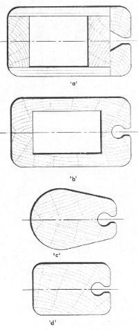 |
FIG. 3-2-Some typical wood mast and boom sections.
Section 'a' is a mast made from plywood which can be relatively easy to
build by the amateur. Section 'b'is made in two halves glued at the
centerline. Because sections 'a'and 'b'are hollow, the halyards
can be run internally. Blocking for reinforcement is provided in the hollow
area, where fittings are located. Section 'c' is a solid wood shaped
mast built in two halves about the centerline in a similar manner. Section
'd' is of single piece wood construction. Sections 'a' 'b
'c, and 'd' have built-in bolt rope grooves. That of section
'a' is easily cut on a saw set to the proper angle. The groove of
sections 'b'and 'c'can be cut before the two parts are
assembled by running the spar angularly over a circular saw with the blade
raised to the proper depth. Optionally, the groove can be cut with a core box
bit and router. The groove in section 'd' must be cut with the core box
bit because of the one-piece construction. Any of these sections could also be
used for the boom if there is a bolt rope in the sail along the foot, and the
boom was properly sized. Boom section 'e' is a typical "T"
configuration which could also be inverted. A track is shown for use with a
sail with slides on the foot. Section 'f' is a rectangular boom used
with loose-footed sails. If stiffness was required, the "T"
configuration could be added, or a square piece added to each side making a
cross-type section. Some degree of flexibility, however, in the boom is
desirable.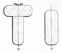 |
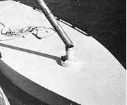
FIG. 3-3 The mast step is any receptacle that maintains the position of the mast in the boat. This sailboard has a mast which consists of a piece of ordinary pipe used to receive the tubular aluminum mast. |
The base of the mast always fits into some type of receptacle or apparatus which is called the MAST STEP. Many types of mast steps are used depending on the configuration desired. Putting the mast in position on the mast step is called STEPPING the mast (see Fig. 9-1). Some masts go through holes in the deck or cabin top and step onto the hull structure, while others bear directly on the deck or cabin top. The simplest type of mast step is the fixed type such as shown by Figs. 3-3 and 3-4. The mast is fixed in position on the step and no movement of the mast is possible, short of removing the mast. Most masts stepped through the deck use fixed steps. Another type is the rotating mast step shown in Fig. 3-5. This type allows the mast to turn or rotate with the direction of the mainsail for greater sail efficiency.
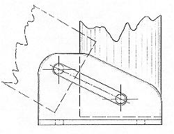
A convenient type of mast step, as far as ease of stepping the mast is concerned, is the pivoting type such as shown in Fig. 3-6. This type allows the mast to be laid into the step fitting, bolted, and pivoted up in position, as opposed to trying to lift it onto the step, which can be tricky, especially on a windy day or if it is a tall mast. With lightweight aluminum spars, it is desirable to use a mast base stiffener at the step when using the pivoting step in order to provide adequate bearing for the pivot bolt.
Many masts require extra reinforcement, and one method of doing this is by utilizing SPREADERS. These are cross members located on the mast at a predetermined location and jutting out sideways. Spreaders are always arranged in pairs, one on each side of the mast. The spreaders "push out" or spread the SHROUDS (the wires supporting the mast from the sides; see Chapter 4) to help stiffen the mast. While spreaders can be made of wood, it is common on small sailboats to have them made of metal tubing, usually stainless steel or aluminum, even when wood masts are used. Some boats do not have any spreaders, while others may have one, two, or more sets. Since spreaders are a necessary evil, (they get in the way and foul things aloft, not to mention added resistance and weight), it is best to have as few as possible.
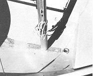 |
FIG. 3-4 This GLEN-L 11 has an adjustable mast step arrangement that allows the boat to be sailed as a cat rig when the mast is moved forward onto the fixed step (to the right), or as a sloop rig when the mast is moved aft along the metal bar base. |
 |
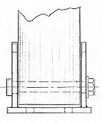
FIG. 3-5 A rotating mast step allows the mast to turn with the boom and sail. This type of step can only be used on certain rigs as all the stays must be arranged in a way to permit the mast to turn. |
 |
 |
|
FIG. 3-6 A pivoting mast step can be made using aluminum or steel plate or channel. The base has two upright plates welded or formed into a "U"-shape, spaced to match the width of the mast. A slot in each |
|
Two types of spreaders are used. One is the fixed-type where the spreader is rigidly mounted to the mast such as shown in Fig. 3-7. The other type is the pivoting or swinging type which is allowed to swing horizontally along a pivot point located on the mast. This type is illustrated in Fig. 3-8. Use the type specified for the boat you have in any case. Where the shrouds pass over or through the spreaders, there should be special fittings or spreader tips which prevent chafing of the shroud by the spreader. Often the spreader tips are adjustable in order to vary the tension of the shrouds. Most spreader tips have an open groove or hole through which the spreader passes. Note that the shrouds are allowed to move or slide on their own against the spreader tip. However, with the open groove type, some means of lashing or taping the shroud to the spreader tip must be provided. The reason for this is that when sailing at an angle of heel, the WINDWARD* shroud will be taut, and the LEEWARD* shroud becomes slack, which could allow the shroud to fall out of the leeward groove if not secured in place.
*WINDWARD - Toward the
direction from which the wind is blowing.
*LEEWARD - Downwind, or with the direction of the wind.
Two other types of spreaders which are used for supplemental strengthening of the mast, or to combat localized stresses, are DIAMOND SPREADERS and JUMPER STRUTS (see Fig. 4-4 'a'). Diamond spreaders are cross members in pairs always used in conjunction with DIAMOND STAYS, which are wire rope stays fixed at either end to the mast. The diamond spreader "spreads out" the diamond stays at their mid-length each side of the mast. The term diamond comes from the fact that when the diamond stays and spreaders are in position, they form a shape like a diamond. An exception to this is when more than one diamond spreader pair is used per stay. Diamond spreaders are just like regular spreaders, except that they are usually smaller and shorter in length.
The jumper strut is usually used only on jibhead rigs to reinforce the upper part of the mast. The jumper strut is located on the forward side of the mast jutting out horizontally forward, and combats the strain of the mainsail pulling aft on the mast. The JUMPER STAY passes through the strut, and is fastened to the mast at each end of the stay. The jumper strut is usually positioned to bisect the length of the jumper stay. Diamond stays and jumper stays are not required on all boats; just on those masts which require additional support.
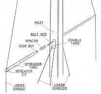
FIG. 3-7 An example of fixed spreaders. This spreader fitting consists of a bolt or threaded rod through the mast, with a spacer on either side, that matches the inside diameter of the spreader tubing. The spreaders are aluminum tubing with sloted tips for the shrouds. This fitting can be used on either wood or aluminum masts. |
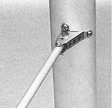
FIG. 3-8 These spreaders pivot on a horizontal plane. The fittings fasten to the sides of the mast and the spreaders are pin-fastened to them. By being able to pivot, the spreaders will align themselves to the ideal position when sailing to windward. |
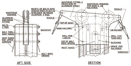
FIG. 3-9 Masthead fitting for a wood mast on a masthead rig. This fitting can be easily made by the home builder. Aluminum plate is used to keep weight to a minimum, which is critical to stability when located aloft. The toggles allow a universal swivel action to the stays, thereby eliminating bending of the stay at the swaged fitting. Note that the halyards are running inside the mast. |
|
The top of the mast is called the MASTHEAD, and depending on the type of rig, the fittings located here will perform various functions. Masthead fittings will also vary depending on whether a wood or aluminum mast is being used. The masthead fitting for wood masts is usually a custom unit made by the builder (see Fig. 3-9). When building a boat using wood spars, it is usually necessary to fabricate a masthead fitting. The designer should provide details for making the masthead fitting. For aluminum masts, the masthead fitting is usually a ready-made unit or "kit"-type assembly to match the mast extrusion, such as illustrated in Figs. 8-4 and 8-5. Obviously a masthead fitting for a masthead rig will be more complex than for a cat or jibhead rig. In any case, the masthead fitting contains at least one SHEAVE (a grooved wheel or pulley) for the main HALYARD, the line used to hoist the sail. With masthead rigs, the masthead fitting has a sheave for the jib halyard as well, and usually incorporates attachment fittings for the stays, and sometimes for the shrouds also. When a sock-type sail is used, and when the mast has no stays, then no masthead fittings are required. In any case, the top of hollow spars should be capped to keep water out. On wood spars this can be a sheet metal cap, and with aluminum spars, the masthead fitting will usually do the job.
On boats where the stays and shrouds do not go to the masthead, but fasten to the mast at some lower point as in jibhead rigs, other means are used to secure stays and shrouds to the mast. With wood spars, the conventional method used to attach the shroud and forestay is to use TANGS. Tangs are short metal straps usually with a crimp or bend to splay them out from the mast when in position. Another type does the same job, but these are of cast metal. The strap type usually has at least two holes; one for the stay attachment, and the other for fastening the tang to the mast. When aluminum masts are used, tangs bolted together through the mast can also be used for the shrouds, but the forestay usually uses another fitting called a HOUND (see Figs. 3-10 and 3-11). The hound wraps around the mast for bearing and has a fitting to receive the forestay. If used on a boat with a jib, then a JIB HALYARD BLOCK (fitting with a sheave used to lead the halyard and change its direction) is attached to the hound. If the shrouds and forestay land at the same point on the mast, then the tangs for the shrouds can be integral with the hound fitting.
 |
 |
|
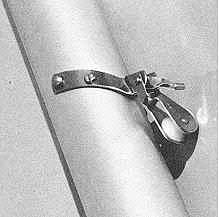
FIG. 3-10 & 3-11 A hound strap fitting for use on jibhead rigs with aluminum spars. The hound provides attachment for the forestay as well as a block for the external jib halyard. The main halyard can be run either internally or externally. If run externally, it would run down the forward side of the mast along with the jib halyard (the most common arrangement on small boats). |
|
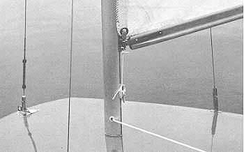
FIG. 3-12 This photo shows several things. First note the relieved area along the mast for the sail bolt rope and gooseneck. The gooseneck has a shackle fitting with a pin through the cringle at the tack of the sail. The downhaul is used to tension the luff of the sail, and the line secures to a jam cleat on the mast. While the mast is aluminum, the boom is made from wood and is in an upsidedown "T" configuration for added strength. A fairlead at the mast base is used for the exit of the internal halyard which runs aft to a jam cleat on the deck. This small sailboat uses a stay adjuster on each shroud with tension adjusted by use of a turnbuckle on the forestay. The shrouds connect to chainplates, while the forestay fastens to a stemhead fitting. |
|
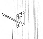
FIG. 3-13 The sheave box is built into the mast at the exit point of the internal halyards to reduce chafe on the halyard. |
|
When using internal halyards (those which run inside the mast), some type of fitting must be provided for the mast where the halyards exit the mast. Internal halyards can only be used in a hollow mast, and where used, they usually exit at or near the mast base. The simplest fitting is merely a hole through the mast fitted with a FAIRLEAD (a fitting to give a line a "fair lead") to prevent chafing the line (see Fig. 3-12). Another arrangement is to use COAMING PULLEYS or SHEAVE BOXES which not only act as a fairlead, but have sheaves incorporated to change direction of the halyards as well as preventing chafing of the line (see Fig. 3-13). These fittings are usually fitted into the mast near the base. In selecting coaming pulleys and sheave boxes, be sure the sheave of the fitting will protrude far enough into the mast so the halyards will not chafe along the inside mast surface.
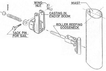
The GOOSENECK is the fitting used to connect the boom to the mast and allow it to move freely, like a universal joint. On the small lateen rig boats the gooseneck is two connected loops which rotate independently (see Fig. 3-14). On conventional rigs, a basic gooseneck is the fixed base type which fastens to the mast. For better sail adjustment, the type of gooseneck which slides on a track or in the mast groove is superior (see Fig. 3-15). Whichever of these types is used, they can be bought as non-swiveling or as a ROLLER REEFING type. The non-swiveling type as shown in Fig. 3-15, does not permit the boom to rotate. The roller reefing type shown in Fig. 3-16, is used so the boom can rotate and allow the sail to be rolled onto the boom in order to reduce sail area when sailing in heavy winds. Goosenecks come in many styles both for wood and aluminum booms with or without the roller reefing feature.
The CLEW OUTHAUL at the other end of the boom is similar in function to the masthead fitting. It is used to attach the clew of the sail to the boom. Where the mainsail is small, the clew outhaul is sometimes nothing more than a line tied to a cleat. Another method is to use a sheave in the end of the boom in order to gain some leverage so the sail can be pulled taut (see Fig. 3-17). With larger mainsails, the clew outhaul is best a slide fitting located on a length of track, or a type which fits into the boom groove if there is one (see Fig. 3-18). On aluminum booms, and especially when roller reefing is used, a boom outhaul fitting is used which performs the clew outhaul function as well as providing a tang for attaching the hardware used to control the sail .
Other incidental fittings may often be attached to the spars as well. CLEATS (a fitting used to belay or secure a line, Fig. 3-19) or BOOM BAILS ("U"-shaped straps used to attach blocks to the boom, Fig. 6-2) are commonly used. A BOOM CRUTCH is another item sometimes used, which is not really a part of the boom. The boom crutch holds up the boom when the sails are furled and when hoisting the sail, in order to keep the boom in its proper position.
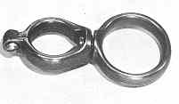
FIG. 3-14 This is a gooseneck used on boats with lateen rigs such as shown in Fig. 2-5. The small loop is secured to the boom while the mast fits loosely into the big loop so that the gooseneck can move freely along the mast. |
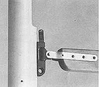
FIG. 3-15-A typical gooseneck showing the tack shackle, downhaul eye, and tangs which lap each side of the boom. Note the relieved area for feeding the sail bolt rope and installing the gooseneck to the mast. |
 |
|
|---|---|
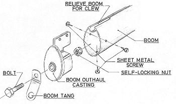
FIG. 3-16-Exploded view of a roller reefing boom assembly. The boom can be pulled aft on the gooseneck and rotated by hand to roll the sail onto the boom. When released, the boom then returns to its position on the gooseneck because of the pressure set up by the spring. The mainsheet fittings are secured to the tang at the aft end of the boom which is secured with the bolt slightly loose so the boom will rotate, while the tang remains stationary. |
|
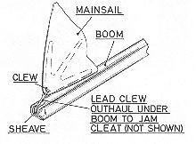 FIG. 3-17-A clew outhaul on a loose-footed sail The boom is slotted at the aft end for a sheave which allows the line to be lead to the underside of the boom where it can be cleated. A simpler type used on very small boats consists of merely a slot or groove in the end of the boom in place of the sheave. |
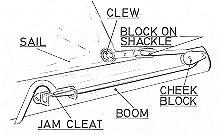
FIG. 3-18-A more sophisticated clew outhaul arrangement uses a line dead-ending on the opposite side of the boom (not visible) and running through a block shackled to the clew of the sail. The line then passes through-a cheek block on the side of the boom and to a jam cleat where it can be belayed. The sail can be secured to the boom with either a bolt rope groove or slides on a track. This arrangement has a built-in power advantage thereby allowing greater tension to be placed along the foot of the sail. |
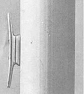
FIG. 3-19-A CLEAT is a fitting to which a rope may be belayed. This metal cleat is fastened to the side of a mast to belay a halyard, and is a typical example of a cleat.