
.....standing rigging
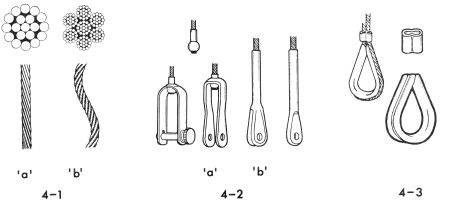
The STANDING RIGGING consists of the wires that hold up and support the mast. Because the mast is in compression and tends to buckle or bend, the standing rigging helps to control the bending. Some small sailboats do not use any standing rigging, and these are said to have free standing unstayed masts (see Figs.2-4 and 2-5). The calculations and methods of figuring the strength of spars and associated rigging are very technical and involved, and should not be undertaken by the novice. Rig your boat as the designer or manufacturer recommends; don't make shortcuts. The material used for the standing rigging is wire rope, usually made from stainless steel, although regular or galvanized steel wire rope is available. Wire rope is measured by the diameter and specified by the composition of the wires used to make up the wire rope (see Fig. 4-1). For example, wire rope designated 1 x 19 would consist of one wire made up of 19 strands. This type is the most common for standing rigging because it is not flexible and is strongest. Another type designated 7 x 19 consists of 7 ropes each consisting of 19 strands. This type, while not as strong, is used where flexibility is important. On boats which use wire rope halyards, the 7 x 19 wire rope is utilized.
 |
|
|---|---|
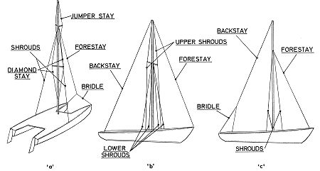
| FIG. 4-1 -Wire rope for rigging is generally in two configurations; stiff and flexible. FL-. 4-1 'a'shows a length and section of 1 x 19 wire rope which is considered stiff. The length is made up of 19 individual strands and is the type usually used for stays. Fig. 4-1 'b' shows a length and section of 7 x 19 wire rope which is a flexible type commonly used - for halyards. The length is made up of seven ropes each consisting of 19 strands. | FIG. 4-2 & 4-3-Common methods of joining fittings to wire rope. Fig. 4-2 'a'shows a swaged ball which can be readily connected to a shackle or forked jaw. Fig. 4-2 'b' shows a swaged fork or jaw and a swaged eye commonly used to connect to tangs, turnbuckles, chainplates, etc. Fig. 4-3 shows a typical Nicopress fitting. The wire rope passes around the thimble and the end is clamped with the special clamp shown. Flexible wire rope is best used with this type of fitting. |
Obviously fittings must be attached to the wire rope for it to do a job, and these fittings can be attached by any of several methods. One method is to SWAGE the fitting to the wire rope. Swaging means that the fitting is compressed cold between a pair of dies., Fig. 4-2 shows some swaged fittings commonly used on small sailboats. Another method is the NICOPRESS fitting, a patented method which uses a sleeve wrapped around the wire forming an eye, and gripping both strands together, as shown in Fig. 4-3. A special vise-like tool is, used to clamp the junction tight. With the Nicopress junction, a THIMBLE (grooved metal ring in the looped eye to prevent chafe) must be used. Because of the bend required in the wire rope at the thimble, flexible wire rope such as 7 x 19 should be used for ultimate strength at the junction.
Special patented-type swageless terminals are also available for joining fittings to wire rope. One type forms a mechanical joint by use of a sleeve barrel fitted over the wire rope and a plug which is inserted into the end of the wire rope. A socket with the fitting attached to it is screwed into the sleeve. The plug inside the sleeve is compressed tightly against the wire rope strands, thereby forming the connection. With this type of junction, the fittings can be disassembled from the wire rope and reused, whereas the swaged fitting cannot. While this type of fitting can be done with ordinary hand tools, a great deal of the strength of the fitting depends on the ability of the person making the junction. Usually swageless fittings are bulkier and heavier than swaged or Nicopress fittings, although arguments exist as to which is stronger. In all cases, the strength of the fitting depends on the quality of the craftsmanship.
A method rarely used today for attaching fittings to wire rope is the zinc socket type connection. This method uses molten zinc poured into the fitting to hold it in place. While still used on some "character" boats and commercial craft, it is considered less reliable than any of the above methods.
STAYS
 |
|
FIG. 4-4 Typical standing rigging configurations. The rig in "a" uses jumper struts which are splayed out diagonally from the mast in order to clear the shrouds. The jumper stays reinforce the mast from the pull caused by the mainsail, as the forestay does not go to the masthead. If the jib is used, this boat would be a jibhead rig. The rig shown by "b" is a typical masthead sloop rig common on boats about 17' and larger. The rig shown by "c" is a typical jibhead rig. The bridle on the backstay is optional and is usually used to provide clearance for an above deck tiller. This arrangement could also be used to provide an adjusting mechanism for varying backstay tension as is common on competitive sailboats. Spreaders and additional shrouds may be used as required on some jibhead rigs. |
The STAYS are wire ropes that support the mast in a fore and aft direction. Technically speaking, any wire that helps support the mast can be called a stay, but in our discussion, we will refer to those at the side of the mast as specifically SHROUDS, described later. Reviewing Fig. 4-4 will aid in following this discussion on stays.
The FORESTAY supports the mast from the forward side and is usually attached to the hull near the forward end of the boat. On a jibhead rig the forestay is attached to the mast about 7/8 the way up from the base. On a masthead rig the forestay attaches to the masthead. On catamarans because of the twin hulls, the forestay often intersects with a BRIDLE, and the bridle is attached to the bow of each hull. A bridle is a line secured at each end with attachment by another line to the middle of the bridle. Some catamarans use a beam between the hulls at the bow and attach the forestay to this beam at the middle in the conventional manner. On single hull boats, the forestay is connected to the hull at the STEMHEAD (forward point of the hull usually at the deck). The forestay must be capable of withstanding considerable strain. The other stay on masthead rigs that complements the forestay is the BACKSTAY. The backstay supports the mast from the aft side, and runs from the masthead to the aft end of the boat. Some backstays connect to a bridle arrangement such as used on the forestay of catamarans previously mentioned. When the bridle is used on the backstay, in most cases it is to allow clearance at the tiller where it pivots across the deck. A backstay is not usually required on small jibhead rigs, but is virtually always used on masthead rigs. Not all backstays are fixed in position. Those that are not, are called "running backstays" and are usually associated with boats of a size not covered in this book.
The stays that support the mast at the sides are called SHROUDS, and it is not correct to call them "side stays" or any other name when they are being referred to specifically. As mentioned previously, not all boats use stays, but boats using a forestay will invariably have at least one shroud per side. When a backstay is not used, the shrouds must take most of the forward tension set up by the forestay, and hence are usually set somewhat aft and outboard of the mast. With jibhead rigs on small boats, there is usually only one shroud per side, attached part way up the mast at some predetermined point. The shrouds are attached to the hull by using CHAINPLATES (shown in Fig. 7-1). Chainplates are straps of metal bolted to the hull to take the strain transmitted by the shrouds.
When the mast requires additional support, two or more sets of spreaders are required, especially on boats which also use a backstay. The set of shrouds which pass through or across the spreader tips and attach to the masthead are called the upper shrouds. They are usually located in line with the side of the mast functioning along the gunwale or rail of the hull or cabin side. The shrouds that join to the mast at the spreader connection are called the lower shrouds, and may connect to the hull forward or aft of the upper shrouds. In some boats it is not uncommon to use two sets of lower shrouds, joining the hull at least several inches apart from each other outboard. The reason shrouds should preferably not junction at a common point is in order to distribute the mast loads over a greater area of the hull.
The shrouds usually attach to the hull via the chainplates, while the forestay attaches to the stemhead fitting, and the backstay to a backstay tang or chainplate. At the spreaders, the upper shrouds should be protected from chafing where they move at the spreader tips. This is best accomplished by-using non-chafing spreader tips. The spreader tips themselves should be rounded or smoothed so as not to chafe or snag the sails.
 |
|
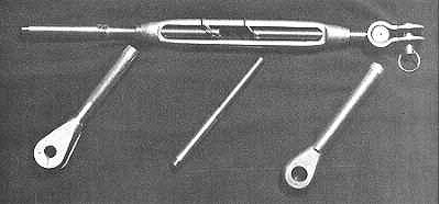
FIG. 4-5 The turnbuckle allows stay tension to be adjusted. This turnbuckle fastens to the chainplate with a jaw fitting and pin, and is swaged to the wire rope stay. Once adjusted, turnbuckles should be locked in position to prevent them from unscrewing. This is also important during transport and storage as it is easy to lose turnbuckle parts and not always easy to replace them. |
As mentioned previously, sometimes supplementary stays are required, and these are usually the diamond stay or jumper stay. They use the same type of wire as other stays although perhaps not as heavy, but they never junction with the hull. All stays and shrouds should have some means of adjustment, and several methods for providing this are commonly used. The most familiar item is the TURNBUCKLE (a fitting with a screw link for tightening the stay) which is available in a variety of types. A typical turnbuckle is shown in Fig. 4-5. Turnbuckles can be attached to the wire rope stays with either a swaged fitting or Nicopress eye and thimble. If the unit is swaged, the turnbuckle must be free to pivot so no bending will occur where the wire enters the swaged area. This is accomplished by using a swivel connector which is integral with the turnbuckle. All turnbuckles should have a means of locking them once the stays have been adjusted. Turnbuckles usually have a jaw and pin which connects them at their lower ends to the chainplate or deck fitting.
Another method of adjusting stays and shrouds is with a STAY ADJUSTER (see Figs. 3-4 and 6-2). The stay adjuster consists of a shaped section of metal, usually stainless steel, with several holes for adjustment. The lower end of the stay adjuster is pinned to the chainplate, while the stay is attached with a pin through any one of the holes in the stay adjuster which give the proper adjustment to the stay. Stay adjusters are less costly than turnbuckles, and when used, no turnbuckle is required for the respective stay. However, stay adjusters are not capable of varying tension on the mast as are turnbuckles, and for this reason, it is common on simple rigs using three stays to use stay adjusters with the shrouds, and a turnbuckle on the forestay which is used to vary the tension once the proper adjustment is set up in the stay adjusters. Once set up, there is no need to ever readjust the stay adjuster, even though the slack stay adjuster to leeward when sailing on a tack could be set up tauter (assuming both sides are readjusted equally) thereby putting more tension in the rig. On rigs with multiple shrouds plus forestay and backstay, it is desirable to use turnbuckles on each stay instead of stay adjusters in order to set each stay properly. It is possible to connect stay adjusters to deck plates in lieu of the chainplate thereby eliminating the need for the chainplate. But, chainplates are more desirable as they distribute the strains imposed by the stays over a larger area.
Another more elaborate device for stay tension adjustment is somewhat like the stay adjuster, but consists of a lever actuator which gives extra power in tensioning the stay. These are called HYFIELD LEVERS (Fig. 4-6) which come in a wide variety of types and sizes, and are often used for tensioning problems other than with stays. Hyfield levers are usually associated with competition-type craft where immediate stay adjustment is required.
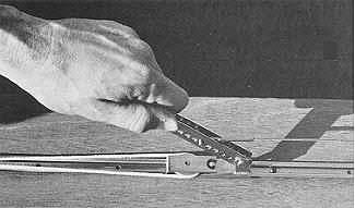 |
FIG. 4-6 Hyfield levers allow tension to be varied, such as along stays. Many types and sizes are available, but are usually only used on competition boats. |
A last means of attaching stays is by means of a simple rope lashing. The rope is merely lashed through rings or thimble eyes attached to the chainplate or bridle on catamarans, and at the lower ends of the stays. Rope lashings should be polyester lines which will not stretch, and should be of ample size. Stays can be attached to the mast in several different manners, part of which may be dictated by whether the mast is made of wood or aluminum. In most cases the stay must be fitted with some form of an eye which will allow it to be attached to the mast via a fitting such as the tang or masthead. As shown in Figs. 4-2 and 4-3, these methods can be a conventional eye, fork or jaw, or a ball joint connected to a fork strap or eye strap. On masthead rigs, it is desirable to give the backstay and fore stay a universal action at the masthead attachment. This can be done with the ball joint type fitting, or by the use of a TOGGLE (a swivel connector as shown in Fig. 3-9). The reason is to prevent bending of the wire rope where it joins to the fitting attached to the wire rope.