
.....outfitting spars
INSTALLING FITTINGS
As noted previously, small boat spars are made of wood or aluminum. Wood spars may be either solid or hollow, while aluminum spars are hollow. Fittings on wood spars are usually screwed with wood screws or through bolted. If through bolted, the bolts should pass through solid wood blocking in hollow spars. Fittings on aluminum spars can be bolted, but the number of through bolts in an aluminum spar should be kept to a minimum, and the bolts should never be tightened to a point that will collapse the spar. Nuts on through bolts should be locked with lock washers or self-locking nuts to prevent the nut from working free. Another method to lock the nut is to cut off the end of the bolt just above the nut and, with a center punch, drive the punch hard into the center of the end of the bolt. This will spread out the metal in the bolt and the nut as well, jamming them in position. Most fittings on aluminum spars are secured with self-threading sheet metal screws that should be of stainless steel. In fact, all fastenings through the aluminum should be stainless steel to prevent corrosion of the spar that can occur when dissimilar metals are in contact in marine conditions. Lubricate sheet metal screws with oil before driving. It is possible to use rivets to fasten parts to the aluminum spars, especially with "pop rivets" if you have the tool. These can be used on items such as tracks or flat base fittings, but in any case the rivets should be stainless steel or aluminum, and the hole of the rivet filled with epoxy cement filler. If using aluminum pop rivets, use plenty because they are not as strong as the stainless steel type. Where plastic fittings are used, such as fairleads, these can be secured with epoxy glue. When drilling for bolts in either wood or aluminum, the hole should not be a sloppy fit, but should be snug. Screw holes for wood screws must also be of the correct size, and lead holes for the self-threading screws in aluminum spars must be of the correct size required for the screw, which is always less than the size of the screw.
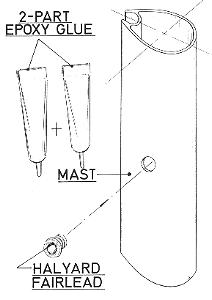 |
FIG. 8-1 - A Nylon fairlead, such as used for the exit point of internal halyards, is simple to install. Just drill a hole of the right size in the mast and use a two-part epoxy adhesive to secure the fitting in position. |
Where internal halyards are required, it is best to lead wires through the mast before outfitting so the halyards can be attached to these for later reeving. On hollow wood masts, it is easiest to do this before assembling the mast. The halyards, when run internally, exit the mast near the base. The exit point must be fitted with some type of fairlead. This may consist of merely a hole with a plastic fairlead fitting such as shown in Fig. 8-1 to prevent chafing the halyard, or can be the more elaborate coaming pulley or sheave box arrangement. In any case, one exit is required for each halyard, and it is convenient to locate the exit for the mainsail halyard on the aft or port side of the mast, and the jib halyard exit on the forward or starboard side of the mast to avoid confusion. Some skippers use different colored lines for halyards to keep them separated. If using wire rope for the halyards, all sheaves must be for use with wire rope, and a fairlead without a sheave should preferably not be used. It is possible to bring the halyards through the mast base where they can be concealed in the cabin, or in the forward cuddy below decks space. This arrangement does have merits especially with regard to clutter. One problem with the arrangement, however, is that there is no good way of keeping water from entering the hull through the holes required, which is especially critical on cabin boats.
8-2 |
8-2 |
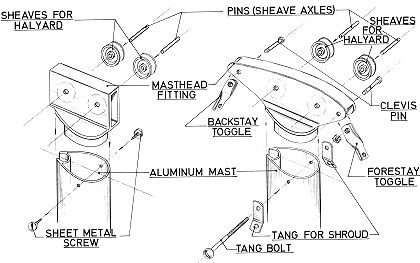
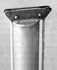
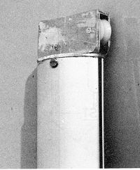
8-4 (left) 8-5 (right) FIG. 8-2 through 8-5 - Masthead fittings used on aluminum masts. Figs. 8-2 and 8-3 are similar, but Fig. 8-2 shows the external halyard carried up one side and down the other utilizing two sheaves at the masthead. Fig. 8-4 shows the exploded assembly of Fig. 8-3, which uses the same halyard arrangement. Optionally, the halyard could be run internally through a hole in the fitting and using a fairlead at the mast base for the exit point. The halyard would then lead only over one sheave. This fitting is intended for cat or jibhead rigs as there are no provisions made for attaching the stays. For use with masthead rigs, something like Fig. 8-5 is used. The halyards run internally through a slot in the cap part of the fitting. The tang bolt may pass through the fitting or just below it, depending on the size of the fitting. |
|
With aluminum spars, most of the other fittings, such as the masthead fitting, or boom gooseneck fittings are made up of aluminum castings which fit the spar extrusion (see Figs. 8-2, 8-3, 8-4, and 8-5). Once the lengths of the spars are known, these fittings are inserted in position and screwed or riveted in place. Aluminum spars are easily cut with a hacksaw if oversize, and rough edges filed clean. When aluminum is used for the boom, it is a simple matter to have roller reefing, as the roller reefing gooseneck can be incorporated in the hollow extrusion. When using aluminum castings for aluminum spars, it is often necessary to file off rough edges. This is normal, and because of the relative softness of the metal, takes little effort. Also, a little oil or wax will make the fittings slip into the extrusion more easily. Fittings on wood spars are fastened with wood screws or through bolted. Goosenecks for wood booms usually have tang or strap-like members into which the boom fits. These tangs can usually be spread apart somewhat to suit the thickness of the boom. The gooseneck is bolted through the boom as are boom bails where required.
Masthead fittings should be detailed by the designer of boats with wood masts, and the larger the boat, the more elaborate the fitting. On simple mastheads which have only one halyard, all that is required is a sheave installed in a groove at the top of the mast. A similar sheave may be used at the clew outhaul on the boom. These sheaves use a pin axle driven through a hole, and the ends are peened (flattened) over to keep it in position. Sheaves are usually synthetic plastic material or metal where wire rope is used.
BOLT ROPE GROOVES
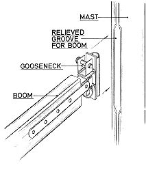
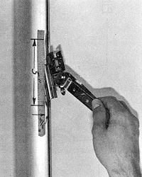
On spars which use a groove for the bolt rope of the sail, there must be a means by which the bolt rope can enter the groove. On wood spars, an area must be relieved using the method described later, or by the directions in the plans provided with the boat, if you are building your own boat. On aluminum spars which use a groove, a portion of the mast must be filed away with a coarse file (see Figs. 8-6 and 8-7). Do not cut away the groove excessively, and make sure all rough edges are smooth to prevent wear on the sail. A small fine file or rotary grinder plus emery cloth will do the job. Look at the end of the mast to determine the amount to remove. The length and position of the cutaway areas should be provided by the designer of the boat, or by the spar supplier. If the position or length required is not given, it can be determined by using the sail as a guide. Hold the sail so the top or head is 6" to 8" below the top of the mast, and stretch the bolt rope tightly along the mast. Mark the position where the tack of the sail falls along the mast, and relieve an area 5" to 12" above the tack, both for entry of the bolt rope and the gooseneck slide fitting. Remember that the relieved portion must be above the gooseneck when the gooseneck is positioned when pulled down by the downhaul (see Fig. 3-15).
 8-6 |
 8-7 |
|
FIG. 8-6 & 8-7 - Goosenecks used with grooved aluminum spars must be relieved in order to fit the gooseneck into the groove. Although a wood boom is shown, it could be of aluminum also. The relieved portion is also required for the bolt rope of the sail so the relieved area must be carefully determined. When the boom is pulled down by the downhaul, it cannot be in the relieved area; it must be below it as shown by Fig. 3-15. |
|
POSITIONING STANDING RIGGING ON MAST
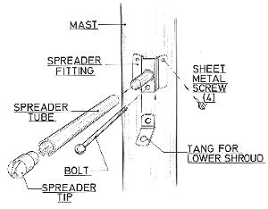
The approximate locations for the attachment points for all the stays and shrouds must be ascertained, either from the plans, or from the spar manufacturer. If the shrouds and stays have already been purchased, this means the attachment points must be located to suit. Otherwise, the builder must determine the lengths required directly from the work. In this case, strings can be attached to the mast, the mast erected temporarily in position, and the lengths determined with the strings. If the stays and shrouds are already purchased, they must be taped or clamped in approximate position on the mast, and the mast temporarily erected. If the stays or shrouds have turnbuckles, these should be set at the midpoint. If the stays and shrouds are long or short in this position, determine the distance and merely shift them along the mast to suit. On boats which use both upper and lower shrouds, first determine the position of the lower shrouds in this manner. The position of the lower shrouds on the mast is also the point of the spreader fitting because these fittings are usually incorporated (see Figs. 8-8, 8-9, and 8-10).
8-8 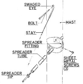
8-9 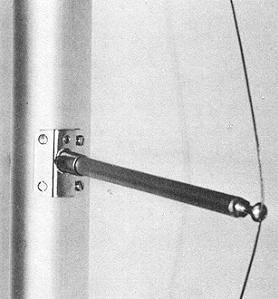
8-10 |
|
FIGS. 8-8 through 8-10 - Two types of spreaders used on aluminum spars are shown. Either type does not pass through the spar. Those shown in Figs. 8-8 and 8-10 can be used on wood masts also. Usually there is a built-in "rake" or angle to the fitting for the spreaders. The lengths of the spreaders can be varied by varying the length of the tubes. That shown in Fig. 8-9 is a type used with diamond stays and does not have any rake built in. Tension is varied in the stay by adjusting the spreader tips in or out. |
When spreaders are used, these must be positioned before fixing the upper shrouds to the mast. Often the position of the spreaders is given "approximate only" by the designer. On hollow wood spars, there should be a length of solid blocking in the mast to allow the spreaders to be shifted up and down the mast several inches as required to suit the length of the stays. On aluminum spars, the spreaders may attach to fittings that screw fasten to the side of the mast, or the spreader fitting may be bolted through the mast. The spreader fittings must align with each other, on each side of the mast, so the force is equalized (see Fig. 8-11). Don't mount one slightly off center from the opposite one. If the fitting is through bolted and an oval mast section is being used, be sure to drill the hole at the widest cross sectional dimension of the spar and at right angles to the longitudinal centerline of the mast cross section. Use a tape measure clipped at the bolt rope groove and wrapped around the girth of the mast to determine the correct point on each side. Then drill the hole from the outside on each side in order to insure that the spreader bolt will align correctly in the mast and be at right angles to the centerline of the boat.
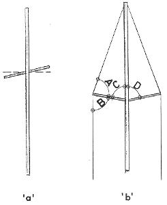 |
FIG. 8-1 I - Spreaders should not be "cocked" or canted from each other. They should be exactly opposite each other to counteract equally the forces imparted to them. When spreaders are raked, ideally Angle "A" should be equal to Angle "B", while Angle "C" and Angle "D" must be equal. |
Some spreaders are mounted so they are horizontal with the waterline. Other spreader fittings are "raked" so the angle formed along the upper shrouds by the spreaders is practically equal (see Fig. 8-11'b'). If the spreader fittings you have are raked, be sure that the rake goes UPWARDS. If the spreaders prove to be too long, most often they can be trimmed off to the desired dimension. Note however, that the dimension of the spreaders out from the mast should be the same on both sides.