
Description of Inboard Marine Hardware Parts
Note: To find the parts listed below, go to the Hardware Index and look up the part by name. A link will take you to the description and part number. The price is looked up on the Price List, by part number. There are links to the Index and Price List at the bottom of each page.
Drawing of a typical direct drive
assembly
Schematic of typical raw water cooling
system
Drawing of a typical powerboat exhaust system
with riser
Shaft Angles &
Layouts
V-Drive?
When you're around this stuff all the time, you forget "v-drive" is not a household word. Serveral boats in our catalog are v-drive boats... meaning they have a rear-mounted inboard motor, with a standard prop shaft. Obviously, if you have the motor at the back and the shaft exiting the boat forward, there has to be something between. That something is a torque tube (drive line) and a gear box that changes the direction of the power. That gear box is a v-drive, so called, because there is an angle between the centerline of the input and output shafts. That angle is typically 10 or 12 degrees.
Since most ski or speed boats under 20' are hurting for room and perform better with less weight, they don't use a transmission. For this reason, v-drives are available with forward only; forward and neutral; or forward, neutral, and reverse; and with various gear ratios.
So why put the motor in the back, and have all this extra hardware? Performance! Our Tornado and Thunderbolt designs are being raced at speeds over 100 mph. Center mounted engine boats usually top out in the 60 to 70 mph range.
Hardware "what's-its" for inboard installations
| 1 2 3 4 5 6 7 8 9 10 11 12 13 14 15 16 17 18 19 |
|---|
If you are unfamiliar with inboard installations, the selection of the proper parts is often difficult. For the novice, we suggest our book, "INBOARD MOTOR INSTALLATIONS".
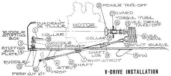
The following is a description of the various parts and their function in an inboard boat. Refer to the "V-Drive Installation" sketch above to determine the location of the parts listed below. Although the sketch depicts a v-drive installation, a direct in-line drive would be similar from the v-drive aft.
DRAWING#1. QUADRANT or CUSTOM TILLER. A quadrant is required when cable type steering is used. The custom tiller is required when single push-pull cable steering is used.
DRAWING#2. RUDDER POST BRACKET. The rudder post bracket supports the upper portion of the rudder. To prevent the rudder from falling through the bottom of the boat, a safety collar is used on the rudder above the rudder post bracket.
DRAWING#3. RUDDER STUFFING BOX. A rudder stuffing box prevents the water from entering the boat through the rudder shaft hole. Various types of seals or packing glands can be used. It is advisable to use the same type for the rudder as for the shaft log (9). The packing-type gland may be repacked while the shaft is in the boat. The seal-type requires that the shaft be removed to replace the rubber Neoprene seal.
DRAWING#4. RUDDER STUFFING BOX PLATE. The rudder stuffing box plate goes on the outside of the boat. It is optional and often not used on the faster boats. It does provide a solid bolting and bearing for the bottom portion of the rudder stuffing box.
DRAWING#5. RUDDER. Rudders of varying size and shape are listed to suit almost any small boat. Rudder Shafts (1" or 1 1/8") must be matched to the rudder stuffing box, collar, and rudder post bracket.
DRAWING#6. STRUT. Struts are available in varying angles and drops to match your installation. Drop is the distance vertically from the base of the strut to the centerline of the strut bearing on the aft end of the strut. Two types of bearings can be obtained for most struts. The Aqua-Lube is a fabric type bearing. The BJ is a rubber-type bearing and is recommended when the boat is to be used in silty waters. Strut bearings are replaceable.
DRAWING#7. WHIP STRUT. Whip struts are used to prevent deflection or whipping of the shaft in high speed boats with flatter shaft angles.
DRAWING#8. FIN. The CUSTOM "V" FIN has a vee in the base to fit the vee in the bottom of most boats. The STREAMLINE FIN has a flat base and is usually intended for smaller boats. The two larger fins are used with the highest speed inboard boats.
DRAWING#9. SHAFT LOG. The shaft log prevents water from coming into the boat through the shaft hole in the bottom of the boat. Shaft logs are available in varying angles to match the shaft or strut angularity. Refer to 3 (RUDDER STUFFING BOX) for information as to the types of packing gland.
DRAWING#10. PROP SHAFT. Shafts come in standard lengths as noted. Shafts can be cut to any desired length and keyed on the driving end without additional cost. As an example, we can cut a shaft 63" and you pay for a 5'6" length. Overall length can be determined by measuring from the coupling in the boat to the aft end of the strut, and adding 5" for 1" shaft, 6" for 1 1/8" shaft. Some ski boats use a shaft that is tapered on both ends. The prop end is a standard taper, the engine end is not. We need additional information to taper this end. There is also an additional charge for tapering the engine end of the shaft.
| As a general rule, the diameter of the propeller should not exceed 14 times the diameter of the prop shaft. There are other factors, such as power, rpm, pitch of propeller, and shaft material that will affect this rule. Below is a practical guide showing appropriate shaft sizes based solely on propeller size. | |
| Propeller Dia. | Shaft Dia. |
|---|---|
| 10" | 3/4" to 7/8" |
| 12" | 7/8" to 1" |
| 14" | 1" to 1 1/8" |
| 16" | 1 1/8" to 1 1/4" |
| 18" | 1 1/4" to 1 3/8" |
| 20" | 1 3/8" to 1 1/2" |
DRAWING
#11. PROPELLERS. For all around use, the
three-blade conventional-type propeller is generally used. Direction of
rotation must be specified. Direction of rotation of the prop is as viewed from
the back of the boat looking forward-left hand counterclockwise; right hand
clockwise. All propellers are intended to fit our propeller shafts and have
standard 1" tapers.
Propeller application chart for various production boats.
#12. PROP NUT KIT. A prop nut kit furnishes the parts necessary to securely hold the propeller on to the shaft.
DRAWING#13. SPLIT SLEEVE COUPLING. This type of coupling is used to connect the propeller shaft to the v-drive output shaft when both output shaft and prop shaft are 1" in diameter.
DRAWING#14. V-DRIVE MOUNT AND V-DRIVE. V-drives can be obtained that include integral forward, neutral and reverse gears. Others contain forward and neutral, while there are those that have no reversing or neutral position. With the latter, a marine transmission should be used on the motor. The exception to the latter statement would be for full race purposes. Ratios of the v-drives will vary. If in doubt, specify the type of boat, its purpose, pleasure or race, the size of motor, and preferably the diameter of the propeller to be turned or the space available for the propeller. We can then estimate the ratio required.
DRAWING#15. V-DRIVE TAKE-OFF. A v-drive flange take-off is used to couple the upper shaft of the v-drive to the torque tube. Refer to TORQUE TUBES (#16) for information regarding series #1310 or #1350.
DRAWING#16. TORQUE TUBE. Torque tubes are used to couple the motor to the v-drive or a jet pump. Two series are available, a #1310 and a #1350. For ordinary use with the conventional pleasure boat and motors to approximately 400 cubic inches and a torque tube 24" or shorter, the #1310 series is satisfactory. For larger engines and for high speed use, the heavy duty #1350 series is desirable. Note that the motor power take-off and the vee drive take-off must be of the correct series to match the torque tube. The torque tube does have "play" in the spline that will make the torque tube approximately 1" shorter or longer than the noted dimensions. If a length other than those listed is needed, the torque tube can be cut and sized to your specifications. Check the price list for cost of this service.
DRAWING#17. TORQUE TUBE GUARD. A torque tube guard protects the boat and occupants if a failure should occur anywhere along the torque tube assembly. Ordinarily, these are desirable on any of the higher speed boats with torque tubes 24" or longer. Note that these are made to accommodate both the #1310 and #1350 torque tube series. (See #16.)
DRAWING#18. SAFETY COLLARS. Safety collars are used on top of the RUDDER POST BRACKET (2) and in high speed craft just aft of the strut or forward of the shaft log as a safety device. Either split or conventional collars are available.
DRAWING#19. POWER TAKE-OFF. A power take-off connects the motor to the torque tube. The Series #1350 or #1310 must match the torque tube. Drives are available for taking the power from the front end, the flywheel end or from a marine transmission. In most cases, the drive will be from the flywheel end. In many cases, driving from the front end is impractical with motors equipped with harmonic balancers or those with small diameter crank shafts at the driving end.