Shop Talk: Small Boat Electrical System
by Terry McIntyre
First, we need to do some design work - what do we want the electrical system to do? My little boat is an inboard, so it must have a bilge blower to meet the USCG ventilation requirements. Although not a formal requirement, I think an electrical bilge pump is something that every boat should have. One thing I really enjoy is a cruise at twilight, so running lights were added to my list. I also wanted a set of instruments (speedometer, fuel, volts) and finally, the engine ignition/starting circuit. That's my "load list". Now, I added up the total electrical current required to run these devices - 5 amps for the lights, 7.5 for the bilge pump, 7.5 for the bilge blower, less than 1 amp for each of the gauges, about 2 for the starter solenoid. Adding these all up says that I might need as much as 25 amps capacity in the (unlikely) situation that everything is running at once. For some margin, I decided to design my system for 40 amps.
Once the loads are known, and the approximate lengths of the wires, the required wire gauge can be found. From a voltage drop table (there is one in Caulder's book, but they are available in many places, including the West Marine catalog) I determined that I needed 12 AWG wire for my main circuits, and 18 AWG wire for the individual loads. Being the conservative engineer that I am, I went one size larger for each - the main supply wire is #10 AWG and the individual circuits are #16 AWG. I also decided to have four circuits - the lights, the blower, the bilge pump, and ignition, which supplies power to the gauges and starter solenoid.
Figure 1 shows a block diagram of how the boat is wired. There is a single positive feed from the battery to the main fuse panel. In accordance with ABYC standards, this feed is protected by an in-line fuse no more than 12 inches from the battery. This fuse should be less than the amperage capacity of the main feed wiring, but more than the maximum expected load; 30 amps
 works in my case. The fuses in each of the circuits are set at 150% the rating of the devices that they drive. Each of the four circuits leaving the feed panel is routed to control switches in the dash, then
to the devices that they power. There are two negative busses (junctions) on the boat, one forward and
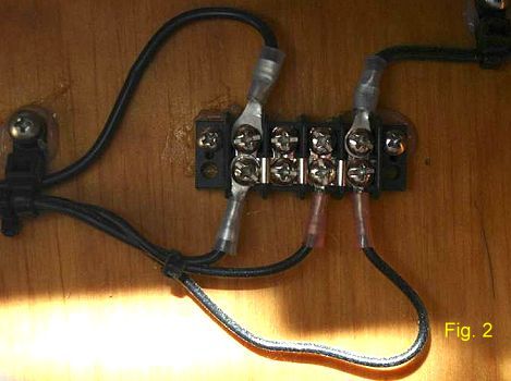
one aft, as the electrical loads tend to be located either around the dash (lights, ignition, and gauges) or near the transom (lights, blower, bilge pump). The aft bus is shown on Figure 2. The negative sides of all the devices are routed to one of the busses, and each buss is connected to the battery negative with a #12 AWG wire.
works in my case. The fuses in each of the circuits are set at 150% the rating of the devices that they drive. Each of the four circuits leaving the feed panel is routed to control switches in the dash, then
to the devices that they power. There are two negative busses (junctions) on the boat, one forward and
one aft, as the electrical loads tend to be located either around the dash (lights, ignition, and gauges) or near the transom (lights, blower, bilge pump). The aft bus is shown on Figure 2. The negative sides of all the devices are routed to one of the busses, and each buss is connected to the battery negative with a #12 AWG wire.
The wiring is all marine grade stranded wire, color-coded red for
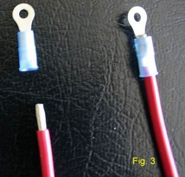 positive, black for negative, yellow for the blower, brown for the bilge pump, white for lights, and several different colors for the ignition and instrumentation circuits. All wires are terminated with marine double crimp ring lugs. Figure 3 shows a stripped wire, a ring lug ready for crimping, and a lug correctly double-crimped to a wire. You will need a decent wire crimper to do this. The insulation is stripped from the wire for only a short distance - about ¼ inch. Then the wire is inserted in the lug, and the lug is then crimped twice, once on the bare part of the wire, to make the electrical connection, and a second time on the insulated section for mechanical strength. Done well, this makes it nearly impossible to pull the lug off the wire. Each lug should be given a good, hard pull test to make sure it is securely crimped.