Inboard Hardware: Rudders
Continued...
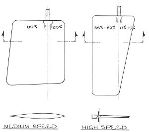 |
Rudders may be either the unbalanced type, or designed with some degree of balance to make turning easier (see Plate 58). An unbalanced rudder has the rudder-stock or pivot point at the extreme forward end of the rudder and all the blade area is aft of this pivot point. On a balanced rudder, there will be a certain portion of the blade area forward of the rudder stock or pivot point which will decrease some of the force necessary to pivot the rudder. However, the portion of the blade forward cannot be too great a percentage of the rudder area as this will make steering too easy as well as dangerous, with constant attention to the helm being required. In general, the balanced rudder will have an area forward of the pivot point of up to 20% of the total rudder area.
Since an appendage under the boat such as a rudder can add considerable drag or resistance to the hull, careful attention is required regarding the size and shape of rudders used, especially on high-speed boats. In cross section, the rudder used for slow and moderate speed boats is usually of the "streamline" or airfoil shape as shown by Plate 58. With this rudder the thickest portion will be 25% to 35% along its length (or "chord" as it is called) from the forward or leading edge. The shape is such that fullness is provided along the contours so that they are convex and not straight or concave. This fullness minimizes resistance and provides the necessary lifting forces for turning efficiency. Rudders that vary from this shape may loose efficiency, stall when turned, and also "chatter" or vibrate. While it would seem that sharp leading and trailing edges would be helpful, actually a slight rounded edge or radius is desirable at the leading edge for less resistance. The radius at the trailing edge can be less, but sharp edges are not practical since they damage easily.
On high-speed craft, a wedge shaped rudder is often used, tapering to a fine leading edge forward. This section provides constant pressure to the rudder blade at all areas at higher speeds, and prevents "burbling" caused by the rudder acting in half air instead of in solid water. The degree of wedge may vary, however 4 degrees included angle is a good average. Most powerboat rudders are made from metal, and certain modifications to the above requirements of both slow-to-medium speed rudders and high-speed rudders may be required to suit the method of manufacture.
On slow and medium speed boats, especially if single screw, a single rudder at the centerline is used, supported where it passes through the hull if of the inboard type, and also at the bottom by a skeg, keel extension, or "deadwood" on most boats of this type (see Plate 57). If the rudder is the outboard type, these are usually hung onto the stern or transom with fittings called "gudgeons and pintles". Readymade or custom-made fittings may be required. Rudders mounted on skegs together with the propeller are afforded considerable protection from damage by the boat's skeg or deadwood and are therefore considered highly safe and reliable.
On high-speed powerboats, the drag created by big rudders and skegs or other underwater appendages can drastically reduce or hinder performance. Consequently, rudders are much smaller in area and are usually of the spade type; that is, hung below the boat by the stock without any other under-water support. Usually such a rudder is mounted directly behind the propeller on either single or twin engine boats so that maximum propeller thrust can be used to aid turning. Because of the smaller rudder area, turning is most effective at high speeds. At slow speeds, these rudders are much less effective, and if the boat has twin screws, the engines are often used for directional control. Hence the reason why high speed planing boats are slow to respond to the helm at slower speeds, and the perpetuated myth that ALL types of boats will handle better with twin engines than single engines. Because spade rudders have no protection from a skeg or deadwood, they are quite vulnerable to damage, along with the propeller, shaft, and strut, especially if of twin screw. Also, the spade rudder stock requires considerable support and strength to withstand the rudder forces since there is no lower support.
POWERBOAT APPLICATIONS
Rudders should be installed so as to turn about 35 degrees from dead center in either direction and not over 40 degrees. More action than this can result in stalling, or an immediate loss of control, and a drastic increase in strain on the rudder, which could damage the rudder or cause it to fail. Stops are therefore provided at some point in the system to prevent greater rudder angles.
The deeper the rudder, the more the hull will tend to bank or lean inboard in a turn. Normally this is not a disadvantage, except that there is often a commensurate loss of speed in sharp turns. Hence, competition boats capable of high speeds prefer flatter turning angles. If the rudder is too deep, stresses on the spade-type rudder can be considerable. This is why an upper steady-rest bearing is necessary to support the spade rudder stock. On the faster boat, rudder proportions usually will be about twice as deep as the width or "chord".
The rudder must not be located where it will suck air. Since the rudder depends on a constant flow of solid water for turning ability, the presence of air will cause an immediate loss of steering action, and possibly cause propeller cavitation or "ventilating" as well. In many cases, especially on the shorter high-speed runabout or racing type boat, the rudder will necessarily have to be located beyond the transom of the boat to suit the propeller shaft angle and clearances. Such a condition will almost always result in the condition described above, and if it occurs, an extension or "plate" must be used over the rudder from the bottom of the boat to prevent air from being sucked in on a turn (see Fig. 16-6). The problem is evidenced by a severe stream of water or "rooster tail" flying up from the transom area, together with a loss of turning ability.
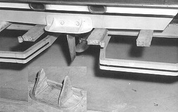 Fig. 16-6 - When the rudder is beyond the transom,
a plate should be mounted over it in line with the bottom of the boat to
prevent air from being sucked in during turning to eliminate steering problems.
Note the wooden mock up of the plate in the inset. This was temporarily bolted
through the drain plug holes to see if this solved the problem before
purchasing and installing the final plate.
Fig. 16-6 - When the rudder is beyond the transom,
a plate should be mounted over it in line with the bottom of the boat to
prevent air from being sucked in during turning to eliminate steering problems.
Note the wooden mock up of the plate in the inset. This was temporarily bolted
through the drain plug holes to see if this solved the problem before
purchasing and installing the final plate. |
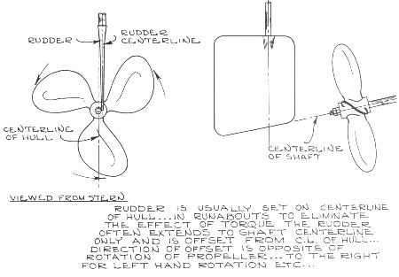
A powerboat will always tend to turn better in the direction the propeller rotates due to the propeller's torque reaction. Offsetting the rudder slightly to one side, as shown by Plate 59 will compensate for this torque reaction to some degree in high speedboats. In the smaller single engine runabout type, this is why it is desirable for the driver of the boat to be seated on the side toward which the propeller rotates. If the propeller turns clockwise, or right-handed, the driver should sit on the right or starboard side to help overcome the torque reaction. Another advantage to offsetting the rudder from the propeller is that it makes removal of the propeller shaft possible without first removing the rudder. On powerboats of slow to medium speed where the rudder is supported at the lower end, a portion of the rudder may be cut away, or a hole may be cut through the rudder, so that when the rudder is turned, the shaft can be removed.
A few examples of rudders available from Glen-L.